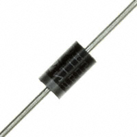
1N5820 THRU 1N5822
SCHOTTKY BARRIER RECTIFIER
Reverse Voltage - 20 to 40 Volts Forward Current - 3.0 Ampere
FEATURES
Plastic package has Underwriters Laboratory Flammability Classification 94V-0 ● Metal silicon junction,majority carrier conduction ● Guardring for overvoltage protection ● Low power loss,high erriciency ● High current capability,low forward voltage drop ● High surge capability ● For use in low voltage,high frequency inverters, free wheeling,and polarity protection applications ● High temperature soldering guaranteed: 250 C/10 seconds,0.375”(9.5mm) lead length, 5 lbs. (2.3kg) tension
●
DO-201AD
1.0 (25.4) MIN. 0.220 (5.6) 0.197(5.0) DIA.
0.375(9.5) 0.285(7.2)
MECHANICAL DATA
Case: JEDEC DO-201AD molded plastic body Terminals: Plated axial leads, solderable per MIL-STD-750, Method 2026 Polarity: Color band denotes cathode end Mounting Position: Any Weight:0.04 ounce, 1.10 grams
0.052 (1.3) 0.048 (1.2) DIA.
1.0 (25.4) MIN.
Dimensions in inches and (millimeters)
MAXIMUM RATINGS AND ELECTRICAL CHARACTERISTICS
Ratings at 25 C ambient temperature unless otherwise specified. Single phase half-wave 60Hz,resistive or inductive load,for current capacitive load derate by 20%.
Characteristic
Maximum repetitive peak reverse voltage Maximum RMS voltage Maximum DC blocking voltage Maximum average forward rectified current 0.375”(9.5mm) lead length at TL=95 C Peak forward surge current 8.3ms single half sine-wave superimposed on rated load (JEDEC Method) Maximum instantaneous forward voltage at 3.0A Maximum DC reverse current TA=25 C at rated DC blocking voltage TA=100 C Typical junction capacitance (NOTE 1) Typical thermal resistance (NOTE 2) Operating junction and storage temperature range
SYMBOLS
1N5820
1N5821
1N5822
UNITS V V V A A
VRRM VRMS VDC I(AV) IFSM VF IR CJ RqJA TJ,TSTG
20 14 20
30 21 30 3.0 80.0
40 28 40
0.475
0.500 2.0 20.0 300.0 40.0 -65 to +125
0.525
V mA pF C/W C
Note:1.Measured at 1MHz and applied reverse voltage of 4.0V D.C. 2.Thermal resistance from junction to ambient at 0.375”(9.5mm)lead length,P.C.B. mounted
1N5820 THRU 1N5822
RATINGS AND CHARACTERISTIC CURVES
FIG.1-TYPICAL FORWARD CURRENT FIG.2-MAXIMUM NON-REPETITIVE PEAK DERATING CURVE FORWARD SURGE CURRENT
100
AVERAGE FORWARD CURRENT,
3.0
PEAK FORWARD SORGE CURRENT,(A)
8.3ms Single Half Sine-Wave Tj (JEDEC Method) =T
50
j max
2.0
(A)
Single Phase
Half Wave 60Hz Load
1.0
Inductive or Resistive 0.375"(9.5mm) Lead Length
1 Cycle
0
10 0.1 10 100
0
20
40
60
80
1005 9
120
140
NUMBER OF CYCLES AT 60HZ FIG.3-TYPICAL INSTANTANEOUS FORWARD CHARACTERISTICS
100
FIG.4-TYPICAL REVERSE CHARACTERISTICS
INSTANTANEOUS FORWARD CURRENT,
10
j
10
INSTANTANEOUS REVERSE CURRENT,
j
1.0
(mA)
(A)
j
1.0
j
Pluse Width=300uS 1% Duty Cycle
0.1
j
0.1
0.01
0
20
40
60
80
100
120
140
0.01
0
0.2
0.4
0.6
0.8
1.0
1.2
1.4
PERCENT OF RATED PEAK REVERSE VOLTAGE,(%)
INSTANTANEOUS FORWARD VOLT AGE,(V) FIG.5-TYPICAL JUNCTION CAPACITANCE
1000
JUNCTION CAPACITANCE,(pF)
100
j
f=1MHz V sig =50mV
10 0.1 1.0 10 100
REVERSE VOLATAGE,(V)
很抱歉,暂时无法提供与“1N5820”相匹配的价格&库存,您可以联系我们找货
免费人工找货