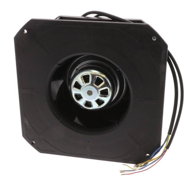
K3G190-RD45-03
Operating instructions
ebm-papst Mulfingen GmbH & Co. KG
Bachmühle 2
D-74673 Mulfingen
Phone +49 (0) 7938 81-0
Fax +49 (0) 7938 81-110
info1@de.ebmpapst.com
www.ebmpapst.com
1. SAFETY REGULATIONS AND INFORMATION
Read these operating instructions carefully before starting work on the
device. Observe the following warnings to prevent malfunctions or
danger to persons.
These operating instructions are to be regarded as part of the device.
The device is only to be sold or passed on together with the operating
instructions.
These operating instructions may be duplicated and distributed to inform
about potential dangers and their prevention.
Translation of the original operating instructions
CONTENTS
1. SAFETY REGULATIONS AND INFORMATION
1
1.1 Hazard levels for warnings
1.2 Staff qualifications
1.3 Basic safety rules
1.4 Voltage
1.5 Safety and protective features
1.6 Electromagnetic radiation
1.7 Mechanical movement
1.8 Emissions
1.9 Hot surface
1.10 Storage
1
1
1
1
2
2
2
2
2
2
2. INTENDED USE
3
3. TECHNICAL DATA
4
3.1 Product drawing
3.2 Nominal data
3.3 Data according to Commission Regulation (EU) 327/2011
3.4 Technical description
3.5 Mounting data
3.6 Transport and storage conditions
3.7 Electromagnetic compatibility
4
6
6
6
7
7
7
4. CONNECTION AND STARTUP
7
4.1 Mechanical connection
4.2 Electrical connection
4.3 Connecting the cables
4.4 Connection diagram
4.5 Checking connections
4.6 Switching on the device
4.7 Switching off the device
7
7
8
9
10
10
10
5. INTEGRATED PROTECTIVE FEATURES
10
6. MAINTENANCE, MALFUNCTIONS, POSSIBLE
CAUSES AND REMEDIES
10
6.1 Cleaning
6.2 Safety inspection
6.3 Disposal
11
11
11
1.1 Hazard levels for warnings
These operating instructions use the following hazard levels to indicate
potentially hazardous situations and important safety regulations:
DANGER
Indicates an imminently hazardous situation which will result in
death or serious injury if the specified actions are not taken.
Compliance with the instructions is imperative.
WARNING
Indicates a potentially hazardous situation which can result in
death or serious injury if the specified actions are not taken.
Exercise extreme caution while working.
CAUTION
Indicates a potentially hazardous situation which can result in
minor or moderate injury or damage to property if the specified
actions are not taken.
NOTE
A potentially harmful situation can occur and, if not avoided, can
lead to property damage.
1.2 Staff qualifications
The device may only be transported, unpacked, installed, operated,
maintained and otherwise used by suitably qualified, trained and
authorized technical staff.
Only authorized specialists are permitted to install the device, to carry
out a test run and to perform work on the electrical installation.
1.3 Basic safety rules
The safety hazards associated with the device must be assessed again
following installation in the final product.
The locally applicable industrial safety regulations are always to be
observed when working on the device.
Keep the workplace clean and tidy. Untidiness in the work area
increases the risk of accidents.
Note the following when working on the device:
; Do not perform any modifications, additions or conversions on the
device without the approval of ebm-papst.
1.4 Voltage
; Check the device's electrical equipment at regular intervals; see
Chapter 6.2 Safety inspection.
; Replace loose connections and defective cables immediately.
DANGER
Electrically charged device
Risk of electric shock
→ When working on an electrically charged device, stand on a
rubber mat.
Item no. 51200-5-9970 · ENU · Change 260701 · Approved 2022-07-01 · Page 1 / 12
ebm-papst Mulfingen GmbH & Co. KG · Bachmühle 2 · D-74673 Mulfingen · Phone +49 (0) 7938 81-0 · Fax +49 (0) 7938 81-110 · info1@de.ebmpapst.com · www.ebmpapst.com
�K3G190-RD45-03
Operating instructions
WARNING
Live terminals and connections even with device
switched off
Electric shock
→ Wait five minutes after disconnecting the voltage at all poles
before opening the device.
CAUTION
In the event of a fault, the rotor and the impeller will be
energized
The rotor and the impeller have basic insulation.
→ Do not touch the rotor and impeller once installed.
CAUTION
If control voltage or a stored speed set value is applied,
the motor will restart automatically, e.g. after a power
failure.
Risk of injury
→ Keep out of the device’s danger zone.
→ When working on the device, switch off the line voltage
and ensure that it cannot be switched back on.
→ Wait until the device comes to a stop.
→ After working on the device, remove any tools or other
objects from the device.
1.5 Safety and protective features
→ Do not wear any loose-fitting or dangling clothing or jewelry
while working on rotating parts.
→ Protect long hair with a cap.
1.8 Emissions
WARNING
Depending on the installation and operating conditions,
the sound pressure level may exceed 70 dB(A).
Risk of noise-induced hearing loss
→ Take appropriate technical safety measures.
→ Protect operating personnel with appropriate safety
equipment such as hearing protection.
→ Also observe the requirements of local agencies.
1.9 Hot surface
CAUTION
High temperature on electronics housing
Risk of burns
→ Ensure sufficient protection against accidental contact.
DANGER
Guard missing and guard not functioning
Without a guard, hands may become caught up in the device
during operation for example, resulting in serious injury. Loose
parts or items of clothing could be drawn in.
1.10 Storage
→ The device is a built-in component. As the owner, you are
responsible for ensuring that the device is adequately
safeguarded.# Operate the device only with a fixed
protective device and guard grill.
; Protect the device against environmental effects and dirt until final
installation.
→ Stop the device immediately if a protective device is
found to be missing or ineffective.
1.6 Electromagnetic radiation
Translation of the original operating instructions
WARNING
Rotating device
Long hair and dangling items of clothing, jewelry and the like
can become entangled and be pulled into the device. Injuries
can result.
Interference from electromagnetic radiation is possible, e.g. in conjunction
with open- and closed-loop control devices.
If impermissible radiation levels occur following installation, appropriate
shielding measures have to be taken by the user.
; Store the device, partially or fully assembled, in a dry place,
protected against the weather and free from vibration, in the original
packaging in a clean environment.
; We recommend storing the device for no longer than one year in
order to guarantee trouble-free operation and the longest possible
service life.
; Even devices explicitly intended for outdoor use are to be stored as
described prior to commissioning.
; Maintain the storage temperature, see
Chapter 3.6 Transport and storage conditions.
NOTE
Electrical or electromagnetic interference after installing
the device in customer equipment.
→ Verify that the entire setup is EMC-compliant.
1.7 Mechanical movement
DANGER
Rotating device
Risk of injury to body parts coming into contact with the rotor or
the impeller.
→ Secure the device against accidental contact.
→ Before working on the system/machine, wait until all
parts have come to a standstill.
Item no. 51200-5-9970 · ENU · Change 260701 · Approved 2022-07-01 · Page 2 / 12
ebm-papst Mulfingen GmbH & Co. KG · Bachmühle 2 · D-74673 Mulfingen · Phone +49 (0) 7938 81-0 · Fax +49 (0) 7938 81-110 · info1@de.ebmpapst.com · www.ebmpapst.com
�K3G190-RD45-03
Operating instructions
2. INTENDED USE
The device is exclusively designed as a built-in device for conveying
air according to its technical data.
Any other usage above and beyond this does not conform with the
intended purpose and constitutes misuse of the device.
Customer equipment must be capable of withstanding the mechanical
and thermal stresses that can arise from this product. This applies for the
entire service life of the equipment in which this product is installed.
Intended use also includes
●
Use of the device in stationary systems only.
●
Performance of all maintenance work.
●
Conveying air at an ambient air pressure between 800 mbar and
1050 mbar.
●
Using the device within the permitted ambient temperature range; see
Chapter 3.6 Transport and storage conditions and
Chapter 3.2 Nominal data.
●
Operating the device with all protective devices.
●
Following the operating instructions.
Improper use
Translation of the original operating instructions
In particular, operating the device in the following ways is prohibited and
could be hazardous:
●
Operating the device in an unbalanced state, e.g. due to dirt deposits
or ice formation.
●
Resonant operation, operation with severe vibration. This also
includes vibration transmitted to the fan from the customer installation.
●
Operation in medical equipment with a life-sustaining or life-support
function.
●
Conveying solids in the flow medium.
●
Painting the device
●
Connections (e.g. screws) coming loose during operation.
●
Conveying air that contains abrasive particles.
●
Conveying highly corrosive air, e.g. salt spray. Exception: devices
designed for salt spray and correspondingly protected.
●
Conveying air with high dust content, e.g. suctioning off sawdust.
●
Operating the device close to flammable materials or components.
●
Operating the device in an explosive atmosphere.
●
Using the device as a safety component or to perform safety-related
functions.
●
Operation with completely or partially disassembled or manipulated
protective devices.
●
In addition, all applications not listed among the intended uses.
Item no. 51200-5-9970 · ENU · Change 260701 · Approved 2022-07-01 · Page 3 / 12
ebm-papst Mulfingen GmbH & Co. KG · Bachmühle 2 · D-74673 Mulfingen · Phone +49 (0) 7938 81-0 · Fax +49 (0) 7938 81-110 · info1@de.ebmpapst.com · www.ebmpapst.com
�K3G190-RD45-03
Operating instructions
3. TECHNICAL DATA
3.1 Product drawing
All dimensions in mm.
1
Translation of the original operating instructions
2
Cable PVC AWG20
3x splice
Cable PVC AWG22
4x splice
Item no. 51200-5-9970 · ENU · Change 260701 · Approved 2022-07-01 · Page 4 / 12
ebm-papst Mulfingen GmbH & Co. KG · Bachmühle 2 · D-74673 Mulfingen · Phone +49 (0) 7938 81-0 · Fax +49 (0) 7938 81-110 · info1@de.ebmpapst.com · www.ebmpapst.com
�K3G190-RD45-03
Operating instructions
3.1.1 Mounting dimensions
Translation of the original operating instructions
All dimensions in mm.
Item no. 51200-5-9970 · ENU · Change 260701 · Approved 2022-07-01 · Page 5 / 12
ebm-papst Mulfingen GmbH & Co. KG · Bachmühle 2 · D-74673 Mulfingen · Phone +49 (0) 7938 81-0 · Fax +49 (0) 7938 81-110 · info1@de.ebmpapst.com · www.ebmpapst.com
�Operating instructions
K3G190-RD45-03
3.2 Nominal data
3.4 Technical description
Motor
M3G055-CF
Phase
Nominal voltage / VAC
Nominal voltage
range / VAC
Frequency / Hz
1~
230
200 .. 240
Method of obtaining
data
Speed (rpm) / min-1
Power consumption / W
Current draw / A
Min. ambient
temperature / °C
Max. ambient
temperature / °C
ml
Weight
Size
Motor size
Rotor surface
Impeller material
Housing material
Number of blades
Direction of rotation
Degree of protection
Insulation class
Moisture (F) /
Environmental (H)
protection class
Installation position
Condensation
drainage holes
Mode
Motor bearing
Technical features
50/60
4120
169
1.35
-25
60
ml = Max. load · me = Max. efficiency · fa = Free air
cs = Customer specification · ce = Customer equipment
Subject to change
3.3 Data according to Commission Regulation (EU) 327/
2011
01 Overall efficiency ηes / %
02 Measurement category
03 Efficiency category
04 Efficiency grade N
05 Variable speed drive
06 Year of manufacture
Translation of the original operating instructions
07 Manufacturer
08 Type
09 Power consumption Ped / kW
09 Air flow qv / m³/h
09 Pressure increase total pfs /
Pa
10 Speed (rpm) n / min-1
11 Specific ratio*
12 Recycling/disposal
13 Maintenance
14 Additional components
*
Actual
Req. 2015
56
A
Static
74.7
Yes
43.3
62
The year of manufacture is specified on the
product's rating label.
ebm-papst Mulfingen GmbH & Co. KG
Amtsgericht (court of registration) Stuttgart ·
HRA 590344
D-74673 Mulfingen
K3G190-RD45-03
0.16
640
455
4070
1.01
Information on recycling and disposal is
provided in the operating instructions.
Information on installation, operation and
maintenance is provided in the operating
instructions.
Components used to calculate the energy
efficiency that are not apparent from the
measurement category are detailed in the
CE declaration.
Specific ratio = 1 + pfs / 100 000 Pa
Data obtained at optimum efficiency level. The efficiency values displayed for achieving
conformity with the Ecodesign Regulation EU 327/2011 has been reached with defined air
duct components (e.g. inlet rings). The dimensions must be requested from ebm-papst. If
other air conduction geometries are used on the installation side, the ebm-papst evaluation
loses its validity/the conformity must be confirmed again. The product does not fall within
the scope of Regulation (EU) 2019/1781 due to the exception specified in Article 2 (2a)
(motors completely integrated into a product).
Touch current
according to IEC
60990 (measuring
circuit Fig. 4, TN
system)
Motor protection
with cable
Protection class
Conformity with
standards
Approval
1.8 kg
190 mm
55
Thick-film passivated
PP plastic
PA plastic
7
Clockwise, viewed toward rotor
IP54
"B"
H1
Any
None, open rotor
S1
Ball bearing
- Output 10 VDC, max. 10 mA
- Tach output
- Power limiter
- Motor current limitation
- Soft start
- Control input 0-10 VDC / PWM
- Control interface with SELV potential
safely disconnected from the mains
- Overvoltage detection
- Thermal overload protection for
electronics/motor
- Line undervoltage detection
50 µC) between phase conductor and
protective earth connection after switching off supply
with multiple devices connected in parallel.
Electric shock, risk of injury
→ Ensure sufficient protection against accidental contact.
Before working on the electrical hookup, short the supply
and PE connections.
Item no. 51200-5-9970 · ENU · Change 260701 · Approved 2022-07-01 · Page 7 / 12
ebm-papst Mulfingen GmbH & Co. KG · Bachmühle 2 · D-74673 Mulfingen · Phone +49 (0) 7938 81-0 · Fax +49 (0) 7938 81-110 · info1@de.ebmpapst.com · www.ebmpapst.com
�K3G190-RD45-03
Operating instructions
CAUTION
Voltage
The fan is a built-in component and has no disconnecting switch.
→ Only connect the fan to circuits that can be switched off with
an all-pole disconnection switch.
→ When working on the fan, secure the system/machine in
which the fan is installed so as to prevent it from being
switched back on.
NOTE
Water ingress into wires or cables
Water ingress at the customer end of the cable can damage the
device.
→ Make sure the end of the cable is connected in a dry
environment.
breakers (RCCB) with a trip threshold of 300 mA and delayed
tripping (super-resistant, characteristic K).
4.2.4 Locked-rotor protection
Due to the locked-rotor protection, the starting current (LRA) is
equal to or less than the nominal current (FLA).
4.3 Connecting the cables
The device has external leads.
; First connect the "PE" (protective earth).
●
Connect the cables according to your application. When doing so,
observe Chapter 4.4 Connection diagram.
Only connect the device to circuits that can be switched off with
an all-pole disconnection switch.
4.2.1 Requirements
; Check whether the information on the nameplate matches the
connection data.
; Before connecting the device, make sure the power supply matches
the device voltage.
; Only use cables designed for the current level indicated on the
nameplate.
For determining the cross-section, note the sizing criteria according
to EN 61800-5-1. The protective earth must have a cross-section
equal to or greater than that of the phase conductor.
We recommend the use of 105 °C cables. Ensure that the minimum
cable cross-section is at least
AWG 26 / 0.13 mm².
Protective earth contact resistance according to EN 60335
Compliance with the resistance specifications according to EN 60335 for
the protective earth connection circuit must be verified in the end
application. Depending on the installation situation, it may be necessary
to connect an additional protective earth conductor by way of the extra
protective earth terminal provided on the device.
Translation of the original operating instructions
4.2.2 Reactive currents
Because of the EMC filter integrated for compliance with EMC
limits (interference emission and immunity to interference),
reactive currents can be measured in the supply line even
when the motor is at a standstill and the line voltage is switched
on.
●
The values are typically in the range < 50 mA
●
At the same time, the effective power in this operating state
(operational readiness) is typically < 2 W.
4.2.3 Residual current circuit breaker (RCCB)
If the use of a residual current device (RCD) is required in your
installation, only pulse-current sensitive and/or AC/DCsensitive residual current devices (type F or B) are
permissible. As with variable frequency drives, residual current
devices cannot provide personal safety while the device is
being operated. When the device power supply is switched on,
pulsed charging currents from the capacitors in the integrated
EMC filter can lead to the residual current devices tripping
instantly. We recommend the use of residual current circuit
Item no. 51200-5-9970 · ENU · Change 260701 · Approved 2022-07-01 · Page 8 / 12
ebm-papst Mulfingen GmbH & Co. KG · Bachmühle 2 · D-74673 Mulfingen · Phone +49 (0) 7938 81-0 · Fax +49 (0) 7938 81-110 · info1@de.ebmpapst.com · www.ebmpapst.com
�Operating instructions
K3G190-RD45-03
4.4 Connection diagram
Drawing preliminary!
Conn.
CON10
CON11
CON12
Designation
L
N
PE
2
4
3
0- 10V PWM
Tach
+10 V
Color
black
blue
green/
yellow
yellow
white
red
1
GND
blue
Function/assignment
Supply connection, power supply, phase, see nameplate for voltage range
Supply connection, power supply, neutral conductor, see nameplate for voltage range
Ground connection
0-10 V / PWM control input, Ri=100 kΩ, SELV
Tach output, open collector, 1 pulse per revolution, Isink max = 10 mA, SELV
Fixed voltage output 10 VDC +/-3 %, Imax. 10 mA, short-circuit-proof, power supply for ext.
devices (e.g. pot), SELV
Reference ground for control interface, SELV
Translation of the original operating instructions
No.
Item no. 51200-5-9970 · ENU · Change 260701 · Approved 2022-07-01 · Page 9 / 12
ebm-papst Mulfingen GmbH & Co. KG · Bachmühle 2 · D-74673 Mulfingen · Phone +49 (0) 7938 81-0 · Fax +49 (0) 7938 81-110 · info1@de.ebmpapst.com · www.ebmpapst.com
�K3G190-RD45-03
Operating instructions
4.5 Checking connections
5. INTEGRATED PROTECTIVE FEATURES
; Ensure isolation from supply (all phases).
; Make sure a restart is impossible
The integrated protective functions cause the motor to switch off
automatically in the event of the faults described in the table.
; Check the cables for proper fit.
Fault
4.6 Switching on the device
Rotor position detection error
Blocked rotor
The device may only be switched on if it has been installed properly and
in accordance with its intended use, including the required safety
mechanisms and professional electrical hookup. This also applies for
devices which have already been equipped with plugs and terminals or
similar connectors by the customer.
WARNING
Hot motor housing
Risk of fire
→ Ensure that no combustible or flammable materials are
located close to the fan.
; Before switching on, check the device for visible external damage
and make sure the protective devices are functional.
; Check the fan's air flow paths for foreign matter and remove any
foreign matter found.
; Apply the nominal supply voltage.
; Start the device by changing the input signal.
NOTE
Damage to the device from vibration
Bearing damage, shorter service life
→ Low-vibration operation of the fan must be ensured over the
entire speed control range.
→ Severe vibration can arise for instance from inexpert
handling, transportation damage and resultant imbalance or
be caused by component or structural resonance.
→ Speed ranges with excessively high vibration levels and
possibly resonant frequencies must be determined in the
course of fan commissioning.
→ Either run through the resonant range as quickly as
possible with speed control or find another remedy.
Translation of the original operating instructions
→ Operation with excessively high vibration levels can
lead to premature failure.
4.7 Switching off the device
Safety feature description/
function
An automatic restart follows.
; After the blockage is
removed, the motor restarts
automatically.
6. MAINTENANCE, MALFUNCTIONS, POSSIBLE
CAUSES AND REMEDIES
Do not perform any repairs on your device. Send the device to ebmpapst for repair or replacement.
WARNING
Live terminals and connections even with device
switched off
Electric shock
→ Wait five minutes after disconnecting the voltage at all poles
before opening the device.
CAUTION
If control voltage or a stored speed set value is applied,
the motor will restart automatically, e.g. after a power
failure.
Risk of injury
→ Keep out of the device’s danger zone.
→ When working on the device, switch off the line voltage
and ensure that it cannot be switched back on.
→ Wait until the device comes to a stop.
→ After working on the device, remove any tools or other
objects from the device.
If the device is out of use for some time, e.g. when in storage,
we recommend switching it on for at least two hours to allow
any condensation to evaporate and to move the bearings.
Malfunction/fault
Impeller not
running smoothly
Possible cause
Imbalance in rotating
parts
Motor not turning
Mechanical blockage
Switching off the device during operation:
; Switch off the device via the control input.
; Do not switch the motor (e.g. in cyclic operation) on and off via power
supply.
Switching off the device for maintenance:
; Switch off the device via the control input.
; Do not switch the motor (e.g. in cyclic operation) on and off via power
supply.
; Disconnect the device from the power supply.
Line voltage faulty
; When disconnecting, be sure to disconnect the ground connection last.
Faulty connection
Possible remedy
Clean the device;
replace it if imbalance
persists after cleaning.
Make sure no
weight clips are
removed during
cleaning.
Switch off, isolate
from supply and
remove mechanical
blockage.
Check line voltage,
restore power
supply, apply control
signal.
Isolate from supply,
correct connection;
see connection
diagram.
Item no. 51200-5-9970 · ENU · Change 260701 · Approved 2022-07-01 · Page 10 / 12
ebm-papst Mulfingen GmbH & Co. KG · Bachmühle 2 · D-74673 Mulfingen · Phone +49 (0) 7938 81-0 · Fax +49 (0) 7938 81-110 · info1@de.ebmpapst.com · www.ebmpapst.com
�Operating instructions
K3G190-RD45-03
Motor/electronics
overtemperature
Deficient cooling
Improve cooling. Let
the device cool down.
To reset the error
message, switch off
the line voltage for at
least 25 s and then
switch it on again.
Ambient temperature Reduce the ambient
too high
temperature.
Reset by reducing
control input to 0.
Impermissible point of Correct the operating
operation
point. Let the device
cool down.
NOTE
High-voltage test
The integrated EMC filter has Y capacitors. The tripping current
is exceeded when AC testing voltage is applied.
→ Test the device with DC voltage when you perform the
legally required high-voltage test. The voltage to be used
corresponds to the peak value of the AC voltage required by
the standard.
; In such cases, switch off the fan immediately and clean it.
What to check
Contact
protection
cover for
intactness or
damage
Device for
damage to
blades and
housing
Fastening the
cables
Fastening the
protective earth
terminal
Insulation of
cables for
damage
Impeller for
wear/deposits/
corrosion and
damage
Abnormal
bearing noise
; The preferred method of cleaning is dry cleaning, e.g. using
compressed air.
6.3 Disposal
In the event of further malfunctions, contact ebm-papst.
6.1 Cleaning
To ensure a long service life, check the fans regularly for proper
operation and soiling. The frequency of checking is to be adapted
accordingly depending on the degree of soiling.
DANGER
Risk of injury from rotating fan.
→ Only clean when not in motion. Do not disconnect the fan
from the power supply, just switch it off via the control input.
This will prevent start-up of the fan.
; Dirt deposits on the motor housing can cause overheating of the motor.
; Soiling of the impeller can cause vibration that will shorten the service
life of the fan.
; Severe vibration can destroy the fan.
; Do not use aggressive cleaning agents!
NOTE
Damage to the device during cleaning
Malfunction possible
Translation of the original operating instructions
6.2 Safety inspection
→ Do not clean the device using a water jet or high-pressure
cleaner.
→ Do not use any acid, alkali or solvent-basedcleaning
agents.
→ Do not use any pointed or sharp-edged objects for cleaning
; Completely remove any cleaning agents used.
; If severe corrosion is visible on load-bearing or rotating parts, switch
off the device immediately and replace it.
; Repair of load-bearing or rotating parts is not permitted!
; Operate the fan for 2 hours at maximum speed so that any water that
has ingressed can evaporate.
How to check How often
Visual inspection At least every
6 months
What action?
Repair or
replacement of
device
Visual inspection At least every
6 months
Replacement of
device
Visual inspection At least every
6 months
Visual inspection At least every
6 months
Fasten
Visual inspection At least every
6 months
Replace cables
Visual inspection At least every
6 months
Clean impeller
or replace device
acoustic
Replace device
At least every
6 months
Fasten
For ebm-papst, environmental protection and resource preservation are
top priority corporate goals.
ebm-papst operates an environmental management system which is
certified in accordance with ISO 14001 and rigorously implemented
around the world on the basis of German standards.
Right from the development stage, ecological design, technical safety
and health protection are fixed criteria.
The following section contains recommendations for ecological disposal
of the product and its components.
6.3.1 Country-specific legal requirements
NOTE
Country-specific legal requirements
Always observe the applicable country-specific legal
regulations with regard to the disposal of products or waste
occurring in the various phases of the life cycle. The
corresponding disposal standards are also to be heeded.
; If cleaning does not eliminate vibrations, the fan may need to be
rebalanced. To have it rebalanced, contact ebm-papst.
; The fan is equipped with maintenance-free ball bearings. The lifetime
lubrication of the ball bearings is designed for a service life of 40,000
hours.
; If bearing replacement is necessary after that period, contact ebmpapst.
; Adapt the maintenance intervals to the actual level of dust exposure.
Item no. 51200-5-9970 · ENU · Change 260701 · Approved 2022-07-01 · Page 11 / 12
ebm-papst Mulfingen GmbH & Co. KG · Bachmühle 2 · D-74673 Mulfingen · Phone +49 (0) 7938 81-0 · Fax +49 (0) 7938 81-110 · info1@de.ebmpapst.com · www.ebmpapst.com
�K3G190-RD45-03
Operating instructions
6.3.2 Disassembly
Disassembly of the product must be performed or supervised by
qualified personnel with the appropriate technical knowledge.
The product is to be disassembled into suitable components for disposal
employing standard procedures for motors.
WARNING
Heavy parts of the product may drop off. Some of the
product components are heavy. These components
could drop off during disassembly.
This can result in fatal or serious injury and material damage.
→ Secure components before unfastening to stop them falling.
6.3.3 Component disposal
The products are mostly made of steel, copper, aluminum and plastic.
Metallic materials are generally considered to be fully recyclable.
Separate the components for recycling into the following categories:
●
Steel and iron
●
Aluminum
●
Non-ferrous metal, e.g. motor windings
●
Plastics, particularly with brominated flame retardants, in accordance
with marking
●
Insulating materials
●
Cables and wires
●
Electronic scrap, e.g. circuit boards
Only ferrite magnets and not rare earth magnets are used in external
rotor motors from ebm-papst Mulfingen GmbH & Co. KG.
; Ferrite magnets can be disposed of in the same way as normal iron
and steel.
Translation of the original operating instructions
Electrical insulating materials on the product, in cables and wires are
made of similar materials and are therefore to be treated in the same
manner.
The materials concerned are as follows:
●
Miscellaneous insulators used in the terminal box
●
Power cables
●
Cables for internal wiring
●
Electrolytic capacitors
Dispose of electronic components employing the proper procedures for
electronic scrap.
→ Please contact ebm-papst for any other questions on disposal.
Item no. 51200-5-9970 · ENU · Change 260701 · Approved 2022-07-01 · Page 12 / 12
ebm-papst Mulfingen GmbH & Co. KG · Bachmühle 2 · D-74673 Mulfingen · Phone +49 (0) 7938 81-0 · Fax +49 (0) 7938 81-110 · info1@de.ebmpapst.com · www.ebmpapst.com
�