Intel® RealSenseTM
D400 Series Product Family
Datasheet
Intel® RealSense™ Vision Processor D4, Intel® RealSense™ Vision
Processor D4 Board, Intel® RealSense™ Depth Module D400, Intel®
RealSense™ Depth Module D410, Intel® RealSense™ Depth Module D415,
Intel® RealSense™ Depth Camera D415, Intel® RealSense™ Depth Module
D420, Intel® RealSense™ Depth Module D430, Intel® RealSense™ Depth
Camera D435, Intel® RealSense™ Depth Camera D435i
Revision 005
January 2019
Document Number: 337029-005
�Intel products described herein. You agree to grant Intel a non-exclusive, royalty-free license to any patent claim thereafter
drafted which includes subject matter disclosed herein.
No license (express or implied, by estoppel or otherwise) to any intellectual property rights is granted by this document.
Intel technologies’ features and benefits depend on system configuration and may require enabled hardware, software or service
activation. Performance varies depending on system configuration. No computer system can be absolutely secure. Check with
your system manufacturer or retailer or learn more at intel.com.
Intel technologies may require enabled hardware, specific software, or services activation. Check with your system manufacturer
or retailer.
The products described may contain design defects or errors known as errata which may cause the product to deviate from
published specifications. Current characterized errata are available on request.
Intel disclaims all express and implied warranties, including without limitation, the implied warranties of merchantability, fitness
for a particular purpose, and non-infringement, as well as any warranty arising from course of performance, course of dealing, or
usage in trade.
All information provided here is subject to change without notice. Contact your Intel representative to obtain the latest Intel
product specifications and roadmaps.
Copies of documents which have an order number and are referenced in this document may be obtained by calling 1-800-5484725 or visit www.intel.com/design/literature.htm.
Intel and the Intel logo, Intel® Core™, Intel® Atom™, trademarks of Intel Corporation in the U.S. and/or other countries.
*Other names and brands may be claimed as the property of others.
© 2019 Intel Corporation. All rights reserved.
2
337029-005
�Description and Features
Contents
1
Description and Features .................................................................................. 11
2
Introduction .................................................................................................... 12
2.1
2.2
2.3
2.4
2.5
2.6
3
12
12
13
15
16
17
Component Specification .................................................................................. 18
3.1
3.2
3.3
3.4
3.5
3.6
3.7
3.8
337029-005
Purpose and Scope of this Document .......................................................
Terminology .........................................................................................
Stereo Vision Depth Technology Overview................................................
Camera System Block Diagram ...............................................................
Intel® RealSense™ Depth Module D400 series Product SKUs ......................
Intel® RealSense™ Depth Camera D400 series Product SKUs .....................
Vision Processor D4 Camera System Components ..................................... 18
Host Processor ..................................................................................... 18
Intel® RealSense™ Vision Processor D4 ................................................... 18
3.3.1
Vision Processor D4 Features .................................................... 18
3.3.2
Vision Processor D4 Signal Description ....................................... 19
3.3.3
Vision Processor D4 Package Mechanical Attributes ...................... 24
3.3.4
Vision Processor D4 Power Requirements.................................... 30
3.3.5
Vision Processor D4 Power Sequencing ....................................... 30
3.3.6
Vision Processor D4 Spec Code .................................................. 31
3.3.7
Vision Processor D4 Storage and Operating Conditions ................. 31
3.3.8
Vision Processor D4 Thermals ................................................... 32
Clock ................................................................................................... 32
Serial (SPI) Flash Memory ...................................................................... 32
Stereo Depth Module ............................................................................. 32
3.6.1
Left and Right Imagers ............................................................. 34
3.6.2
Infrared Projector .................................................................... 35
3.6.3
Color Sensor ........................................................................... 36
3.6.4
Depth Module Connector .......................................................... 37
3.6.5
Stereo Depth Module Label ....................................................... 37
3.6.6
Stiffener ................................................................................. 38
3.6.7
Temperature Sensor ................................................................ 38
3.6.8
Other Stereo Depth Module Components .................................... 38
3.6.9
Mechanical Dimensions............................................................. 39
3.6.10 Stereo Depth Module Power Sequence........................................ 40
3.6.11 Stereo Depth Module Storage and Operating Conditions ............... 40
Intel® RealSense™ Vision Processor D4 Board .......................................... 41
3.7.1
Mechanical Dimensions............................................................. 42
3.7.2
Depth Module Receptacle .......................................................... 42
3.7.3
Flex and Rigid Interposer Interconnect ....................................... 42
3.7.4
External Sensor Sync Connector ................................................ 47
3.7.5
USB Peripheral Connector – Type-C ........................................... 47
3.7.6
Color Image Signal Processor (ISP) ............................................ 49
3.7.7
Vision Processor D4 Board Power Requirements .......................... 49
3.7.8
Vision Processor D4 Board Thermals .......................................... 49
3.7.9
Vision Processor D4 Board Storage and Operating Conditions ........ 50
3.7.10 Intel® RealSense™ Vision Processor D4 Board Product Identifier and
Material Code .......................................................................... 50
Intel® RealSense™ Depth Camera D400 Series ......................................... 50
3
�3.8.1
Depth Camera D400 Series Mechanical Dimensions ..................... 51
3.8.2
Depth Camera D400 Series Thermals ......................................... 52
3.8.3
Depth Camera D400 Series Storage and Operating Conditions ...... 52
(1) Controlled conditions should be used for long term storage of product. (2)
Short exposure represents temporary max limits acceptable for
transportation conditions. ......................................................... 53
3.8.4
Depth Camera D400 Series Product Identifier and Material Code ... 53
3.8.5
Camera Lens Cleaning Procedure ............................................... 53
4
Functional Specification .................................................................................... 54
4.1
4.2
4.3
4.4
4.5
4.6
4.7
4.8
4.9
4.10
4.11
4.12
5
5.2
Intel® RealSense™ Software Development Kit 2.0 ..................................... 70
System Integration .......................................................................................... 71
7.1
7.2
7.3
7.4
7.5
7.6
7.7
7.8
7.9
4
Update ................................................................................................ 69
5.1.1
Update Limits .......................................................................... 69
Recovery ............................................................................................. 69
Software......................................................................................................... 70
6.1
7
54
54
57
57
58
60
60
62
63
65
66
67
68
Firmware ........................................................................................................ 69
5.1
6
Vendor Identification (VID) and Device Identification (DID) ........................
Vision Processor D4 Data Streams ..........................................................
Depth Field of View (FOV) ......................................................................
Depth Field of View at Distance (Z) .........................................................
Invalid Depth Band ...............................................................................
Minimum-Z Depth .................................................................................
Depth Quality Specification ....................................................................
Measured Power ...................................................................................
Depth Start Point (Ground Zero Reference) ..............................................
4.9.1
Depth Origin X-Y Coordinates ....................................................
Depth Camera Functions ........................................................................
Color Camera Functions .........................................................................
IMU Specifications.................................................................................
System Level Block Diagram ..................................................................
Vision Processor D4 System Integration ...................................................
7.2.1
Vision Processor D4 Board ........................................................
7.2.2
Vision Processor D4 on Motherboard ..........................................
D4 Camera System Power Delivery .........................................................
Vision Processor D4 Board for Integrated Peripheral ..................................
7.4.1
USB 3.1 Gen 1 Receptacle ........................................................
7.4.2
USB 3.1 Gen 1 High Speed Cable Assembly ................................
7.4.3
Transmit to Receive Crossover ..................................................
7.4.4
Motherboard Receptacle ...........................................................
7.4.5
Vision Processor D4 Board for Integrated Peripheral Power
Requirements..........................................................................
Thermals .............................................................................................
Stereo Depth Module Flex ......................................................................
Stereo Depth Module Mounting Guidance .................................................
7.7.1
Screw Mount ...........................................................................
7.7.2
Bracket Mount .........................................................................
7.7.3
Stereo Depth Module Air gap.....................................................
Thermal Interface Material .....................................................................
Heat Sink .............................................................................................
71
71
71
72
73
74
74
74
75
76
76
76
78
78
78
79
81
81
81
337029-005
�Description and Features
7.10
7.11
7.12
7.13
7.14
7.15
8
Cover Design and Material Guidance .......................................................
Gaskets ...............................................................................................
7.11.1 Optical Isolation ......................................................................
7.11.2 Dust Protection .......................................................................
Firmware Recovery ...............................................................................
Calibration Support ...............................................................................
Multi-Camera Hardware Sync .................................................................
Handling Conditions ..............................................................................
81
82
83
84
84
85
85
86
Platform Design Guidelines ............................................................................... 87
8.1
8.2
8.3
9
Vision Processor D4 on Motherboard ....................................................... 87
Kaby Lake U and Kaby Lake Y platforms .................................................. 88
8.2.1
Kaby Lake Platform Introduction ................................................ 88
8.2.2
Supported PCB Stack-Up and Routing Geometries ....................... 88
8.2.3
Vision Processor D4 on Motherboard with USB Host Interface ........ 89
8.2.4
Vision Processor D4 on Motherboard with MIPI Host Interface ....... 90
8.2.5
Vision Processor D4 Board for Integrated Peripheral (USB 3.1 Gen 1
Host to Vision Processor D4 Routing) ......................................... 92
8.2.6
USB2.0 Design Guidelines (USB2 Host to Vision Processor D4
Routing) ................................................................................. 93
Cherry Trail T4 Platform......................................................................... 94
8.3.1
Cherry Trail T4 Platform Introduction ......................................... 94
8.3.2
Vision Processor D4 Platform Design Guidelines ........................... 94
Regulatory Compliance ..................................................................................... 95
9.1
9.2
System Laser Compliance ......................................................................
9.1.1
Certification Statement.............................................................
9.1.2
Explanatory Label ....................................................................
9.1.3
Cautionary Statements .............................................................
9.1.4
Manufacturer’s Information .......................................................
9.1.5
US FDA Accession Number ........................................................
9.1.6
NRTL Statement ......................................................................
Ecology Compliance ..............................................................................
9.2.1
China RoHS Declaration ............................................................
9.2.2
Waste Electrical and Electronic Equipment (WEEE) .......................
95
95
95
95
96
96
96
97
97
98
10
Mechanical Drawings ........................................................................................ 99
11
Connector Drawings ........................................................................................ 107
12
Appendix A – Vision Processor D4 on Motherboard Schematic Checklist ................. 109
12.1
13
Power Delivery .................................................................................... 116
Appendix B- Cover Material .............................................................................. 119
Figures
Figure
Figure
Figure
Figure
Figure
2-1.
2-2.
2-3.
3-1.
3-2.
Active Infrared (IR) Stereo Vision Technology .........................................................
Depth Measurement (Z) versus Range (R) ..............................................................
Vision Processor D4 Camera System Block Diagram ................................................
Vision Processor D4 Package Drawing ....................................................................
Vision Processor D4 Ball-out .................................................................................
337029-005
14
14
15
26
27
5
�Figure
Figure
Figure
Figure
Figure
Figure
Figure
Figure
Figure
Figure
Figure
Figure
Figure
Figure
Figure
Figure
Figure
Figure
Figure
Figure
Figure
Figure
Figure
Figure
Figure
Figure
Figure
Figure
Figure
Figure
Figure
Figure
Figure
Figure
Figure
Figure
Figure
Figure
Figure
Figure
Figure
Figure
Figure
Figure
Figure
Figure
Figure
Figure
Figure
Figure
Figure
Figure
3-3. Vision Processor D4 Power Sequencing .................................................................. 31
3-4. Stereo Depth Module (Intel® RealSense™ Depth Module D410)................................. 33
3-5. Stereo Depth Module (Intel® RealSense™ Depth Module D430)................................. 33
3-6. Stereo Depth Module Power Sequence ................................................................... 40
3-7. Vision Processor D4 Board (USB Peripheral Type-C)................................................. 41
3-8. Flex Interposer (Illustration) ................................................................................. 43
3-9. Rigid Interposer (Illustration) ............................................................................... 43
3-10. Depth Module Receptacle and Plug Connector Pin Position ...................................... 44
3-11. Depth Module Connector Orientation and Pin Position............................................. 46
3-12. USB Type-C Receptacle Pin Map .......................................................................... 48
3-13. Intel® RealSenseTM Depth Camera D415 ............................................................... 50
3-14. Intel® RealSense™ Depth Camera D435/D435i ..................................................... 51
4-1. Depth Field of View to Depth Map illustration .......................................................... 58
4-2. Left Invalid Depth Band ....................................................................................... 59
4-3. Depth Module Depth Start Point Reference ............................................................. 63
4-4. Depth Camera Depth Start Point Reference ............................................................ 64
4-5. Depth Module X-Y Depth Origin Reference .............................................................. 65
4-6. Depth Camera X-Y Depth Origin Reference ............................................................. 66
7-1. System Block Diagram ......................................................................................... 71
7-2. Intel® RealSense™ Vision Processor D4 Board ........................................................ 72
7-3. Vision Processor D4 on Motherboard (Illustration) ................................................... 72
7-4. D4 Camera System Power Scheme ........................................................................ 73
7-5. Host Motherboard USB 3.1 Gen 1 Routing .............................................................. 75
7-6. Receptacle Ground Bar Motherboard Connections .................................................... 76
7-7. Bottom Stiffener Depth Module D410 ..................................................................... 78
7-8. Bottom Stiffener Depth Module D430 ..................................................................... 78
7-9. Stereo Depth Module Screw Mount ........................................................................ 79
7-10. Stereo Depth Module Bracket .............................................................................. 79
7-11. Stereo Depth Module Bracket Mount .................................................................... 80
7-12. Stereo Depth Module Bracket Install .................................................................... 80
7-13. Stereo Depth Module Air Gap .............................................................................. 81
7-14. Illustration of Gasket Placement and Cover Material ............................................... 83
7-15. Example of Light Leakage Effects......................................................................... 84
7-16. Firmware Recovery Sequence ............................................................................. 85
7-17. External Sensor Sync Connector Location on D4 Vision Processor D4 Board .............. 85
7-18. External Sensor Sync Connector Location on Depth Camera D435/D435i .................. 86
8-1. Vision Processor D4 with USB Host Interface .......................................................... 87
8-2. Vision Processor D4 with MIPI Host Interface .......................................................... 87
8-3. Vision Processor D4 on Board for USB Integrated Peripheral ..................................... 88
8-4. Host Processor - Vision Processor D4 ..................................................................... 89
8-5. Vision Processor D4 Transmit - Host Receive ......................................................... 90
8-6. Stereo Depth Transmit - Vision Processor D4 Receive .............................................. 91
8-7. Flex Interposer PCB Stack-Up ............................................................................... 92
8-8. USB 3.1 Gen 1 Host to Vision Processor D4 Topology ............................................... 92
8-9. USB2.0 Host to Vision Processor D4....................................................................... 93
9-1. NRTL Certifications .............................................................................................. 97
10-1. Intel® RealSense™ Depth Module D400 ................................................................ 99
10-2. Intel® RealSense™ Depth Module D410 ............................................................... 100
10-3. Intel® RealSense™ Depth Module D415 ............................................................... 101
10-4. Intel® RealSense™ Depth Module D420 ............................................................... 102
10-5. Intel® RealSense™ Depth Module D430 ............................................................... 103
10-6. Vision Processor D4 Board USB Type-C (Intel® RealSense™ Vision Processor D4
Board)........................................................................................................... 104
Figure 10-7. Intel® RealSense™ Depth Camera D415 .............................................................. 105
Figure 10-8. Intel® RealSense™ Depth Camera D435/D435i .................................................... 106
6
337029-005
�Description and Features
Figure
Figure
Figure
Figure
Figure
Figure
11-1.
11-2.
12-1.
12-2.
12-3.
12-4.
Receptacle Mechanical Drawing (50 Pin Depth Module Receptacle).......................... 107
Plug Mechanical Drawing (50 pin Depth Module Plug) ............................................ 108
Vision Processor D4 Laser PWM Reference Platform Schematic ............................... 116
Vision Processor D4 24MHz Crystal Clock Reference Platform Schematic .................. 116
DC-DC Reference Platform Schematic (3.3V, 1.8V, 0.9V) ....................................... 117
Vision Processor D4 VDD_PG and AVDD Reference Platform Schematic ................... 118
Tables
Table
Table
Table
Table
Table
Table
Table
Table
Table
Table
Table
Table
Table
Table
Table
Table
Table
Table
Table
Table
Table
Table
Table
Table
Table
Table
Table
Table
Table
Table
Table
Table
Table
Table
Table
Table
Table
Table
Table
Table
Table
Table
Table
2-1. Depth Module Product SKU Descriptions ..................................................................
2-2. Depth Camera Product SKU Descriptions .................................................................
3-1. Component Descriptions ........................................................................................
3-2. Vision Processor D4 Signal Descriptions ..................................................................
3-3. Hardware Straps ..................................................................................................
3-4. Vision Processor D4 Package Mechanical Attributes ...................................................
3-5. Vision Processor D4 Ball-out by Signal Name ...........................................................
3-6. Vision Processor D4 Power Requirements ................................................................
3-7. Vision Processor D4 Power Sequencing Timing Parameters ........................................
3-8. Vision Processor D4 SPEC Code ..............................................................................
3-9. Vision Processor D4 Storage and Operating Conditions ..............................................
3-10. Stereo Depth Module...........................................................................................
3-11. Stereo Depth Module SKU Properties .....................................................................
3-12. Standard Left and Right Imager Properties ............................................................
3-13. Wide Left and Right Imager Properties ..................................................................
3-14. Standard Infrared Projector Parameters ................................................................
3-15. Wide Infrared Projector Parameters ......................................................................
3-16. Color Sensor Properties .......................................................................................
3-17. Depth Module 50-pin Connector Plug Details ..........................................................
3-18. Stereo Depth Module Product Labeling ..................................................................
3-19. Stereo Depth Module Label Fields .........................................................................
3-20. Intel® RealSense™ Depth Module D400 Series Product Identifier Code and Product
Material Code ..................................................................................................
3-21. Other Stereo Depth Module Components ...............................................................
3-22. Intel® RealSense™ Depth Module D400 Mechanical Dimensions ...............................
3-23. Intel® RealSense™ Depth Module D410 Mechanical Dimensions ...............................
3-24. Intel® RealSense™ Depth Module D415 Mechanical Dimensions ...............................
3-25. Intel® RealSense™ Depth Module D420 Mechanical Dimensions ...............................
3-26. Intel® RealSense™ Depth Module D430 Mechanical Dimensions ...............................
3-27. Stereo Depth Module Storage and Operating Conditions ..........................................
3-28. Vision Processor D4 Board ..................................................................................
3-29. Vision Processor D4 Board Components .................................................................
3-30. Vision Processor D4 USB Type-C Board Mechanical Dimensions ................................
3-31. Depth Module Receptacle Details ..........................................................................
3-32. Interposer Interconnect Signal Description............................................................
3-33. Custom Flex Interposer Ordering Logistics .............................................................
3-34. External Sensor Connector Details ........................................................................
3-35. External Sensor Sync Connector Pin List ................................................................
3-36. USB Peripheral Connector Pin List .........................................................................
3-37. Custom USB Type C cable Assemblies Ordering Logistics .........................................
3-38. ISP Properties ....................................................................................................
3-39. Vision Processor D4 Board Power Requirements .....................................................
3-40. Vision Processor D4 Board Storage and Operating Conditions ...................................
3-41. Vision Processor D4 Board Product Identifier and Material Code ................................
337029-005
16
17
18
19
24
25
27
30
30
31
31
32
33
34
34
35
35
36
37
37
37
38
38
39
39
39
39
40
40
41
41
42
42
44
46
47
47
48
49
49
49
50
50
7
�Table
Table
Table
Table
Table
Table
Table
Table
Table
Table
Table
Table
Table
Table
Table
Table
Table
Table
Table
Table
Table
Table
Table
Table
Table
Table
Table
Table
Table
Table
Table
Table
Table
Table
Table
Table
Table
Table
Table
Table
Table
Table
Table
Table
Table
Table
8
3-42. Depth Camera SKU properties .............................................................................. 51
3-43. Intel® RealSense™ Depth Camera D415 Mechanical Dimensions ............................... 51
3-44. Intel® RealSense™ Depth Camera D435, D435i Mechanical Dimensions .................... 52
3-45. Max Skin Temperature ........................................................................................ 52
3-46. Depth Camera D400 Series Storage and Operating Conditions ................................. 52
3-47. Depth Camera D400 Series Product Identifier and Material Code .............................. 53
4-1. Vendor ID and Device ID Table .............................................................................. 54
4-2. Image Formats (USB 3.1 Gen1) ............................................................................. 54
4-3. Image Formats (USB 2.0) ...................................................................................... 55
4-4. Simultaneous Image Streams (USB 3.1 Gen1 & USB2.0) ........................................... 56
4-5. Depth Field of View ............................................................................................... 57
4-6. Minimum-Z Depth ................................................................................................ 60
4-7: Depth Quality Metric ............................................................................................. 60
4-8: Depth Quality Metric Illustration ............................................................................. 61
4-9. Depth Quality Specification .................................................................................... 61
4-10. Power- Ubuntu 16.04 .......................................................................................... 62
4-11. Power – Windows 10 (RS4) .................................................................................. 62
4-12. Depth Module Depth Start Point .......................................................................... 63
4-13. Depth Cameras Depth Start Point ........................................................................ 64
4-14. Depth Module X-Y Depth Origin Coordinates.......................................................... 65
4-15. Depth Camera X-Y Depth Origin Coordinates ......................................................... 66
4-16. Depth Camera Controls ....................................................................................... 66
4-17. RGB Exposed Controls ......................................................................................... 67
4-18. IMU Specifications .............................................................................................. 68
7-1. USB 3.1 Gen 1 Receptacle Characteristics................................................................ 74
7-2. USB 3.1 Gen 1 Receptacle Pin Out .......................................................................... 74
7-3. USB 3.1 Gen 1 Plug Characteristics ......................................................................... 74
7-4. Cable Assembly Specification ................................................................................. 75
7-5. Motherboard Receptacle Properties ......................................................................... 76
7-6. Vision Processor D4 Board as Embedded Peripheral Power Requirements .................... 76
7-7. Vision Processor D4 Board – Component Power and TDP at Max Operating Mode(1) ....... 77
7-8. Stereo Depth Module (Standard) – Component Power and TDP at Max Operating
Mode(1) ........................................................................................................... 77
7-9. Stereo Depth Module (Wide) – Component Power and TDP at Max Operating Mode(1) .... 77
7-10. Vision Processor D4 Board Components – Case Temperature Limits (Still Air) ............ 77
7-11. Bracket Ordering Logistics ................................................................................... 80
7-12. Component Transmission ..................................................................................... 82
7-13. Electrostatic Discharge Caution ............................................................................ 86
8-1. Host Transmit – Vision Processor D4 Receive Routing Guidelines ................................ 89
8-2. Vision Processor D4 Transmit - Host Receive Routing Guidelines ................................ 89
8-3. Vision Processor D4 Transmit – Host Receive Routing Guidelines ................................ 90
8-4. Stereo Depth Module Transmit - Vision Processor D4 Receive Routing Guidelines ........ 91
8-5. USB 3.1 Gen 1 Host to Vision Processor D4 Routing Guidelines ................................. 93
9-1. U.S. FDA Accession Number................................................................................... 96
12-1. Vision Processor D4 on Motherboard Schematic Checklist ....................................... 109
12-2. Vision Processor D4 Decoupling and Filter Requirements ........................................ 118
13-1. Example: Cover Material Parameters .................................................................... 119
337029-005
�Description and Features
Revision History
Document Number
Revision Number
Description
Revision Date
337029
001
Initial release
January 2018
002
Tracking Module 1 removal, NRTL
certification, 7.2.2.1 Firmware Update
March 2018
003
Added USB2.0 support
July 2018
Removed VBUS0 from Table 3 6.Vision
Processor D4 Power Requirements
Table 3 12. Standard Left and Right
Imager Properties
Table 3 13. Wide Left and Right
Imager Properties
Table 3 9. Vision Processor D4 Storage
and Operating Conditions
Table 3 27 Stereo Depth Module
Storage and Operating Conditions
Table 3 38. Vision Processor D4 Board
Storage and Operating Conditions
Table 3 44. Depth Camera D400 Series
Storage and Operating Conditions
Table 4 3. Image Formats (USB 2.0)
Table 4 5. Simultaneous Image
Streams (USB3.1 Gen1, USB 2.0)
4.7 Depth Origin Point (Ground Truth
Zero)
7.14 Multi-Camera hardware sync for
multi-camera configuration
337029-005
9
�Document Number
Revision Number
004
Description
Description and Features
Revision Date
November 2018
Terminology
Table 2-2. Depth Camera Product SKU
Descriptions
Table 3-11. Stereo Depth Module SKU
Properties
Table 3-33. Custom Flex Interposer
Ordering Logistics
Table 3-35. External Sensor Sync
Connector Pin List
Table 3-42. Depth Camera SKU
properties
Table 3-47. Depth Camera D400 Series
Product Identifier and Material
Code
Table 4-1. Vendor ID and Device ID
Table
Table 4-2. Image Formats (USB 3.1
Gen1)
Table 4-3. Image Formats (USB 2.0)
Table 4-9. Depth Quality Specification
Section 4-12 IMU Specification
005
Table 3-11. Stereo Depth Module SKU
Properties
January 2019
Table 3-42. Depth Camera SKU
Properties
Table 4-4. Simultaneous Image
Streams (USB 3.1 Gen 1 & USB
2.0)
Table 4-18. IMU Specifications
§§
10
337029-005
�Description and Features
1
Description and Features
Description
Usages/Markets
The Intel® RealSenseTM D400 series is a stereo
vision depth camera system. The subsystem
assembly contains stereo depth module and vision
processor with USB 2.0/USB 3.1 Gen 1 or MIPI1
connection to host processor.
Drones
Robots
Home and Surveillance
Virtual Reality
PC Peripherals
The small size and ease of integration of the
camera sub system provides system integrators
flexibility to design into a wide range of products.
Minimum System Requirements
USB 2.0/USB 3.1 Gen 1
The Intel® RealSenseTM D400 series also offers
complete depth cameras integrating vision
processor, stereo depth module, RGB sensor with
color image signal processing and Inertial
Measurement Unit2 (IMU). The depth cameras are
designed for easy setup and portability making
them ideal for makers, educators, hardware
prototypes and software development.
Ubuntu*16.xx/Windows*10
The Intel® RealSenseTM D400 series is supported
with cross-platform and open source Intel®
RealSense™ SDK 2.0
Intel® RealSense™ Depth Camera D415
Features
Intel® RealSense™ Vision Processor D4
Up to 1280x720 active stereo depth resolution
Up to 1920x1080 RGB resolution
Depth Diagonal Field of View over 70°
Dual rolling shutter sensors for up to 90 FPS
depth streaming
Range 0.3m to over 10m (Varies with lighting
conditions)
Features
2nd Generation Stereo Depth Camera System
2nd Generation dedicated Intel® RealSense™
Vision Processor D4 with advanced algorithms
Infrared (IR) Laser Projector System (Class 1)
Full HD resolution Image sensors
Intel® RealSense™ Depth Camera
D435/D435i Features
Intel® RealSense™ Vision Processor D4
Up to 1280x720 active stereo depth resolution
Active Power Management
Up to 1920x1080 RGB resolution
Selection of Stereo Depth Module options to
meet your usage requirements
Depth Diagonal Field of View over 90°
Dual global shutter sensors for up to 90 FPS
depth streaming
1. MIPI is not currently supported. Please
contact your Intel representative on MIPI
enablement timelines.
Range 0.2m to over 10m (Varies with lighting
conditions)
Intel® RealSense™ Depth Camera D435i
includes Inertial Measurement Unit (IMU) for 6
degrees of freedom (6DoF) data
2. Camera SKU dependent
§§
Datasheet
11
�Introduction
2
2.1
Introduction
Purpose and Scope of this Document
This document captures the specifications and the design–in details for the Intel®
RealSense™ D400 series family of products. This document provides information
necessary to understand and implement an Intel® RealSense™ D400 series based
camera system.
Note: Intel® RealSense™ D400 series is alternately referred as “D4 Camera System”
in this document. Intel® RealSense™ Vision Processor D4 is alternately referred as
“D4” in this document.
2.2
Terminology
Term
Description
6DOF
Six degrees of freedom (6DoF) refers to the freedom of movement of a rigid
body in three-dimensional space. Forward/back, up/down, left/right, pitch,
yaw, roll
Stereo Depth
Baseline
The distance between the center of the left and right imagers in a stereo
camera
MIPI CSI-2
The Camera Serial Interface (CSI) is a specification of the Mobile Industry
Processor Interface (MIPI) Alliance and CSI-2 is the 2nd generation
specification defining the interface between a camera and a host processor
Depth
Depth video streams are like color video streams except each pixel has a
value representing the distance away from the camera instead of color
information
D4 (DS5)
If the term D4 is used alone, it refers to the entire D4 camera system
consisting of various modules and components.
If the term D4 is used with an appropriate qualifier (i.e. D4 Vision Processor,
D4 Vision Processor Board), it refers to the specific module or component
within the D4 camera system.
12
FOV
Field Of View (FOV) describes the angular extent of a given scene that is
imaged by a camera. A camera's FOV can be measured horizontally,
vertically, or diagonally
Host System
Computer or SOC connected to D4 camera
I2C
I²C (Inter-Integrated Circuit), pronounced I-squared-C, is a multi-master,
multi-slave, single-ended, serial computer bus invented by Philips
Semiconductor (now NXP Semiconductors). It is typically used to allow easy
control and data communication between components.
IR Projector
This refers to the source of infrared (IR) light used for illuminating a scene,
object, or person to collect depth data.
337029-005
�Introduction
Term
2.3
Description
Imagers
Depth camera system uses a pair of cameras referred as imagers to calculate
depth. They are identical cameras configured with identical settings.
Image Signal
Processor (ISP)
Image processing functions to enhance color image quality
Left imager
From the perspective of the stereo camera looking out at the world, the left
imager is on the left side of the camera module. Thus, when the user is
facing the D4 camera, the left imager is actually on the right side of the
camera module.
Lens
This refers to the optical component of an imager in the D4 camera. Its
purpose is to focus the incoming light rays onto the CMOS chip in the imager.
MIPI
MIPI (Mobile Industry Processor Interface) is a global, open membership
organization that develops interface specifications for the mobile ecosystem
Platform
camera
This refers to the two-dimensional (2D) color camera on platform
System On
Chip (SoC)
Integrated circuit (IC) that integrates all components of a computer
Stereo Depth
Module
This refers to a stiffened module containing at least two imagers. The
distance between the imagers, which is referred to as the baseline or
intraocular spacing, is typically in the range of 20 mm to 70 mm.
Stereo camera
This refers to a pair of imagers looking at the same subject from slightly
different perspectives. The difference in the perspectives is used to generate
a depth map by calculating a numeric value for the distance from the imagers
to every point in the scene.
SKU
Stock Keeping Unit (SKU) is a unique identifier for distinct products. It is
often used in the scope of naming different versions of a device
TBD
To Be Determined. In the context of this document, information will be
available in a later revision.
Stereo Vision Depth Technology Overview
The Intel® RealSense™ D400 series depth camera uses stereo vision to calculate
depth. The stereo vision implementation consists of a left imager, right imager, and an
optional infrared projector. The infrared projector projects non-visible static IR pattern
to improve depth accuracy in scenes with low texture. The left and right imagers
capture the scene and sends imager data to the depth imaging (vision) processor,
which calculates depth values for each pixel in the image by correlating points on the
left image to the right image and via shift between a point on the Left image and the
Right image. The depth pixel values are processed to generate a depth frame.
Subsequent depth frames create a depth video stream.
337029-005
13
�Introduction
Figure 2-1. Active Infrared (IR) Stereo Vision Technology
2) Search
1) Capture
3) Depth
Image
Sensors
IR Projector
The depth pixel value is a measurement from the parallel plane of the imagers and not
the absolute range as illustrated.
Figure 2-2. Depth Measurement (Z) versus Range (R)
14
337029-005
�Introduction
2.4
Camera System Block Diagram
The camera system has two main components, Vision processor D4 and Depth
module. The Vision processor D4 is either on the host processor motherboard or on a
discrete board with either USB2.0/USB 3.1 Gen1 or MIPI connection to the host
processor. The Depth module incorporates left and right imagers for stereo vision with
the optional IR projector and RGB color sensor. The RGB color sensor data is sent to
vision processor D4 via the color Image Signal Processor (ISP) on Host Processor
motherboard or D4 Board.
Figure 2-3. Vision Processor D4 Camera System Block Diagram
337029-005
15
�Introduction
2.5
Intel® RealSense™ Depth Module D400 series
Product SKUs
Table below describes main components that make up the different depth module
SKUs
Table 2-1. Depth Module Product SKU Descriptions
Component
Subcomponent
D400
D410
D415
D420
D430
Intel® RealSense™
Vision Processor D4
-
√
√
√
√
√
Standard Stereo Imagers
√
√
√
X
X
Wide Stereo Imagers
X
X
X
√
√
Standard Infrared
Projector
X
√
√
X
X
Wide Infrared Projector
X
X
X
X
√
RGB color sensor
X
X
√
X
X
Intel® RealSense™
Depth Module
D400
D410
D415
D420
D430
16
-
Intel®
Intel®
Intel®
Intel®
Intel®
RealSense™ Depth Module D400
RealSenseTM Depth Module D410
RealSenseTM Depth Module D415
RealSenseTM Depth Module D420
RealSenseTM Depth Module D430
337029-005
�Introduction
2.6
Intel® RealSense™ Depth Camera D400 series
Product SKUs
Table below describes main components that make up the different camera SKUs:
Table 2-2. Depth Camera Product SKU Descriptions
Component
Subcomponent
Intel®
RealSenseTM
Depth Camera
D415
Intel®
RealSenseTM
Depth Camera
D435
Intel®
RealSenseTM
Depth Camera
D435i
Intel®
RealSense™
Vision
Processor D4
-
√
√
√
Standard Stereo
Imagers
√
X
X
Wide Stereo Imagers
X
√
√
Standard Infrared
Projector
√
X
X
Wide Infrared
Projector
X
√
√
RGB color sensor
√
√
√
X
X
√
Intel
RealSense™
Depth Module
®
Inertial
Measurement
Unit (IMU)
§§
337029-005
17
�Component Specification
3
3.1
Component Specification
Vision Processor D4 Camera System Components
Table 3-1. Component Descriptions
Component
Description
Host Processor
Host Processor that receives Depth and other data streams from Vision
Processor D4
Vision
Processor D4
(DS5 ASIC)
Depth Imaging Processor with USB 2.0/USB 3.1 Gen 1 or MIPI interface
connection to Host Processor
Clock
24MHz clock source for Vision Processor D4
Serial Flash
Memory
SPI 16Mb Serial Flash memory for firmware storage
Stereo Depth
Module
Camera module with left and Right Imager, Color Sensor†, IR projector†
enclosed in a stiffener
Power Delivery
Circuitry on motherboard/Vision processor D4 Board to deliver and manage
power to Vision Processor D4 and Stereo Depth Module.
Stereo Depth
Connector and
Interposer
50 pin connector on motherboard/Vision Processor D4 Board and Stereo
Depth module with interposer for connection
(†) SKU dependent
3.2
Host Processor
The host processor interface to Vision Processor D4 is either USB 2.0/USB 3.1 Gen 1
or MIPI. To ensure the best of quality of service, the Vision Processor D4 must be
connected to a dedicated USB 3.1 Gen 1 root port within the host processor system.
3.3
Intel® RealSense™ Vision Processor D4
The primary function of Vision Processor D4 is to perform depth stereo vision
processing. The Vision Processor D4 on Host Processor motherboard or on Vision
Processor D4 Board communicates to the host processor through USB2.0/USB 3.1 Gen
1 or MIPI and receives sensor data from stereo depth module. The Vision Processor
D4 supports MIPI CSI-2 channels for connection to image sensors.
3.3.1
Vision Processor D4 Features
18
28nm Process Technology.
337029-005
�Component Specification
3.3.2
5 MIPI camera ports with each MIPI lane capable of handling data transfers of up
to 750 Mbps.
USB2.0/USB 3.1 Gen 1 or MIPI interface to host system.
Image rectification for camera optics and alignment compensation
IR Projector (Laser) controls
Serial Peripheral Interface for fast data transfer with external SPI flash.
Integrated I2C ports
General purpose Input Output pins
Active power gating
Vision Processor D4 Signal Description
Table 3-2. Vision Processor D4 Signal Descriptions
RESERVED – Signal reserved for future usage
IO Type- Input Output Buffer type
A – Analog
I – Input
O - Output
Signal Name
IO
Type
After
RESET
Host MIPI Data Lane 0 Differential Pair
A
I
Host MIPI Data Lane 1 Differential Pair
A
I
Host MIPI Data Lane 2 Differential Pair
A
I
Host MIPI Data Lane 3 Differential Pair
A
I
Host MIPI Clock Differential Transmit Pair
A
I
I/O
IO
A
I
Imager A MIPI Data Lane 0 Differential Receive Pair
A
I
Imager A MIPI Data Lane 1 Differential Receive Pair
A
I
Description
Host MIPI
H_DATAP0
H_DATAN0
H_DATAP1
H_DATAN1
H_DATAP2
H_DATAN2
H_DATAP3
H_DATAN3
H_CLKP
H_CLKN
H_SDA
H_SCL
H_REXT
Host I2C Bus Data and Clock
Host MIPI External Reference 6.04K 1% resistor pull down
to ground)
Imager A MIPI
A_DATAP0
A_DATAN0
A_DATAP1
A_DATAN1
337029-005
19
�Component Specification
IO
Type
After
RESET
A
I
Imager A I2C Bus Data and Clock
I/O
IO
A_RCLK
Imager A Reference Clock
I/O
O
A_PDOWN
(RESERVED) Imager A Power Down Signal
I/O
O
A_VSYNC
Imager A Vertical/Frame Sync
I/O
I
A_RESETN
Imager A Reset
I/O
O
A_REXT
Imager A MIPI External Reference (6.04K 1% resistor pull
down to ground)
A
I
A
I
(RESERVED) Imager B MIPI Data Lane 1 Differential
Receive Pair
A
I
(RESERVED) Imager B MIPI Clock Differential Receive Pair
A
I
(RESERVED) Imager B I2C Bus Data and Clock
I/O
IO
B_RCLK
(RESERVED) Imager B Reference Clock
I/O
O
B_PDOWN
(RESERVED) Imager B Power Down
I/O
O
B_VSYNC
(RESERVED) Imager B Vertical/Frame Sync
I/O
I
B_RESETN
(RESERVED) Imager B Reset
I/O
O
B_REXT
Imager B MIPI External Reference (6.04K 1% resistor pull
down to ground)
A
I
Imager M MIPI Data Lane 0 Differential Receive Pair
A
I
Imager M MIPI Data Lane 1 Differential Receive Pair
A
I
Imager M MIPI Clock Differential Receive Pair
A
I
Imager M I2C Bus Data and Clock
I/O
IO
M_RCLK
Imager M Reference Clock
I/O
O
M_PDOWN
(RESERVED) Imager M Power Down
I/O
O
M_VSYNC
Imager M Vertical/Frame Sync
I/O
I
Signal Name
A_CLKP
A_CKLN
A_SDA
A_SCL
Description
Imager A MIPI Clock Differential Receive Pair
Imager B MIPI
B_DATAP0
B_DATAN0
B_DATAP1
B_DATAN1
B_CLKP
B_CKLN
B_SDA
B_SCL
(RESERVED) Imager B MIPI Data Lane 0 Differential
Receive Pair
Imager M MIPI
M_DATAP0
M_DATAN0
M_DATAP1
M_DATAN1
M_CLKP
M_CKLN
M_SDA
M_SCL
20
337029-005
�Component Specification
IO
Type
After
RESET
I/O
O
A
I
Imager Y MIPI Data Lane 0 Differential Receive Pair
A
I
Imager Y MIPI Data Lane 1 Differential Receive Pair
A
I
Imager Y MIPI Clock Differential Receive Pair
A
I
Imager Y I2C Bus Data and Clock
I/O
IO
Y_RCLK
Imager Y Reference Clock
I/O
O
Y_PDOWN
(RESERVED) Imager Y Power Down
I/O
O
Y_VSYNC
Imager Y Vertical/Frame Sync
I/O
I
Y_RESETN
Imager Y Reset
I/O
O
Y_REXT
Imager Y MIPI External Reference (6.04K 1% resistor pull
down to ground)
A
I
(RESERVED) Imager Z MIPI Data Lane 0 Differential
Receive Pair
A
I
(RESERVED) Imager Z MIPI Data Lane 1 Differential
Receive Pair
A
I
(RESERVED) Imager Z MIPI Clock differential Receive Pair
A
I
(RESERVED) Imager Z I2C Bus Data and Clock
I/O
IO
Z_RCLK
(RESERVED) Imager Z Reference Clock
I/O
O
Z_PDOWN
(RESERVED) Imager Z Power Down
I/O
O
Z_VSYNC
Depth Vertical/Frame Sync
I/O
O
Z_RESETN
(RESERVED) Imager Z Reset
I/O
O
Z_REXT
Imager Z MIPI External Reference (6.04K 1% resistor pull
down to ground)
A
I
Signal Name
Description
M_RESETN
Imager M Reset
M_REXT
Imager M MIPI External Reference (6.04K 1% resistor pull
down to ground)
Imager Y MIPI
Y_DATAP0
Y_DATAN0
Y_DATAP1
Y_DATAN1
Y_CLKP
Y_CKLN
Y_SDA
Y_SCL
Imager Z MIPI
Z_DATAP0
Z_DATAN0
Z_DATAP1
Z_DATAN1
Z_CLKP
Z_CKLN
Z_SDA
Z_SCL
Serial Peripheral Interconnect (SPI)
337029-005
SPI_DI
SPI Data Input
I/O
I
SPI_DO
SPI Data Output
I/O
O
SPI_CLK
SPI Clock
O
O
21
�Component Specification
Signal Name
Description
IO
Type
After
RESET
SPI_CS
SPI Chip Select
O
O
SPI_WP
Flash Write Protect
O
O
General Purpose Input Output (GPIO)
GPIO[0]
(RESERVED) Not Defined
I/O
I
GPIO[1]
(RESERVED) Not Defined
I/O
I
GPIO[2]
Laser PWM – Controls Laser Power for IR projector on
Stereo Module
I/O
O
GPIO[3]
(RESERVED) Not Defined
I/O
I
GPIO[4]
(RESERVED) Not Defined
I/O
I
GPIO[5]
(RESERVED) Not Defined
I/O
I
GPIO[6]
(RESERVED) Not Defined
I/O
I
GPIO[7]
(RESERVED) Not Defined
I/O
I/O
EGPIO[0]
(RESERVED) Not Defined
I/O
I/O
EGPIO[1]
(RESERVED) Not Defined
I/O
I/O
EGPIO[2]
(RESERVED) Not Defined
I/O
I/O
EGPIO[3]
Laser_PWRDN - IR projector Power Down Signal
I/O
O
EGPIO[4]
(RESERVED) Not Defined
I/O
I/O
EGPIO[5]
FLAGB – IR Projector Fault Detect
I/O
I
EGPIO[6]
(RESERVED) Not Defined
I/O
I/O
EGPIO[7]
(RESERVED) Not Defined
I/O
I/O
EGPIO[8]
ISP_FCS (Color ISP)
I/O
O
EGPIO[9]
(RESERVED) Not Defined
I/O
I/O
EGPIO[10]
(RESERVED) Not Defined
I/O
I/O
EGPIO[11]
(RESERVED) Not Defined
I/O
I/O
EGPIO[12]
(RESERVED) Not Defined
I/O
I/O
EGPIO[13]
(RESERVED) - For Intel test purpose only
I/O
I/O
Miscellaneous
22
LD_ON_OUT_XX
(RESERVED) Laser Enable
O
O
MODSTROB
(RESERVED) Modulation current strobe
O
O
MODSIGN
(RESERVED) Modulation current sign
O
O
LD_ERR
Laser Error (Active High)
I
I
CLKXI
24MHz XTAL
I
I
CLKXO
24MHz XTAL
I
I
PRSTN
D4 Reset
I
I
CW_CSR_PRSTn
Hardware reset without debug port reset
I/O
I
337029-005
�Component Specification
Signal Name
Description
IO
Type
After
RESET
PMU_PWR_EN
Switchable domain (VDD_PG) power control signal
I/O
O
DFU
Dynamic FW update, used for FW recovery
I/O
I
I2C Bus Data and Clock
I/O
IO
ISP_SCL
ISP_SDA
VQPSQ
(RESERVED) – For Intel test purpose only
O
O
VQPSM
(RESERVED) – For Intel test purpose only
O
O
REFPADCLKP
(RESERVED) – For Intel test purpose only
I
I
REFPADCLKM
(RESERVED) – For Intel test purpose only
I
I
JTAG
TDI
Test Data Input
I/O
I
TDO
Test Data Output
I/O
O
TCLK
Test Clock Input
I/O
I
TMS
Test Mode Select
I/O
I
TRSTN
Test Reset
I/O
I
USB
USB_RXP
USB 3.1 Gen 1 receive, positive side
A
I
USB_RXN
USB 3.1 Gen 1 receive, negative side
A
I
USB_TXP
USB 3.1 Gen 1 Transmit, positive side
A
O
USB_TXN
USB 3.1 Gen 1 Transmit, negative side
A
O
USB_DP
USB 2.0 D+ line
A
IO
USB_DN
USB 2.0 D- line
A
IO
USB_ID
Mini-receptacle identifier and test point
USB_RESREF
Reference Resistor input. 200 Ohm 1%
A
I
Power and Ground
337029-005
VDD
0.9V (Core Voltage)
Power
VDD_PG
0.9V (Switched Core Voltage)
Power
USB_DVDD
0.9V (USB Core Voltage)
Power
VPTX0
0.9V (USB Core Voltage)
Power
VP
0.9V (USB Core Voltage)
Power
*_AVDD
1.8V (MIPI Core and IO Voltage)
Power
VDDPLL
0.9V (PLL Voltage)
Power
VDDTS
1.8V (Temperature Sensor Voltage)
Power
VDDPST18
1.8V (IO Voltage)
Power
USB_VDD330
3.3V (USB Core Voltage)
Power
23
�Component Specification
Signal Name
IO
Type
Description
VBUS0
3.3V (VBUS power monitor)
VSS
Ground
GND
*_AGND
Ground
GND
After
RESET
Power
Table 3-3. Hardware Straps
Pin
EPGPIO0
Boot
Load
No
HW/FW
FW
Description
USB connection type:
0: Peripheral (default)
1: Integrated
EGPIO4
Yes
HW
SPI Interface:
0: SPI on “Z”
1: SPI connected (default)
EPGPIO7
Yes
FW
Flash
00: 64Mbit
01: 8Mbit
10: 16 Mbit (default)
EPGPIO8
11: 32 Mbit
EPGPIO9
No
FW
Host interface:
0: USB (default)
1: MIPI
EPGPIO10
No
FW
Board version [0] (default: 0)
EPGPIO11
No
FW
Board version [1] (default: 0)
EPGPIO12
No
FW
Board version [2] (default: 0)
DFU
Yes
HW
Go to DFU
0: Disabled (default)
1: Go to DFU mode (Recovery)
NOTES:
Boot Load – Read during Boot
Hardware (HW) Strap – External hardware pin state directly configures D4 functionality
Firmware (FW) Strap – External hardware pin state is read by firmware and firmware
configures D4 functionality
3.3.3
Vision Processor D4 Package Mechanical Attributes
Table below provides an overview of the mechanical attributes of the package.
24
337029-005
�Component Specification
Table 3-4. Vision Processor D4 Package Mechanical Attributes
Pin
Boot Load
HW/FW
Package Technology
Package Type
FlipChip CSP (Chip Scale Package)
Interconnect
Ball Grid Array (BGA) Ball
Lead Free
Yes
Halogenated Flame Retardant Free
Yes
Solder Ball Composition
SAC125Ni
Ball/Pin Count
225 solder balls
Grid Array Pattern
15 x 15
Nominal Package Size (mm)
6.40 x 6.40
Min Ball/Pin pitch (mm)
0.42
Package Configuration
Package Dimensions
Weight
337029-005
~1 gm
25
�Component Specification
Figure 3-1. Vision Processor D4 Package Drawing
26
337029-005
�Component Specification
Figure 3-2. Vision Processor D4 Ball-out
A
B
C
D
E
F
G
H
J
K
L
15
VSS
Y_DATAN0
Y_REXT
Y_SCL
GPIO_0
GPIO_1
GPIO_5
GPIO_6
MODSTROB
TMS
TRSTN
14
Y_CLKN
Y_CLKP
Y_DATAP0
Y_RCLK
Y_SDA
GPIO_3 MODSIGN
TCLK
TDO
SPI_CLK SPI_MOSI Z_RESETN Z_VSYNC
14
VSS
VSS
13
B_SDA
Y_AVDD
VSS
VSS
VSS
13
Y_DATAN1 Y_DATAP1
12
B_DATAN0
11
10
B_SCL
B_CLKN B_DATAP0 B_REXT
B_DATAN1
Y_RESETN GPIO_2
Y_PDOWN Y_VSYNC
H_DATAN3 B_DATAP1 B_PDOWN
VSS
8
H_DATAN2 H_DATAP3 B_VSYNC
VSS
VSS
7
H_CLKN H_DATAP2 B_RCLK
H_AVDD
VSS
6
H_DATAN1
5
H_DATAN0 H_DATAP1
H_CLKP
H_AVDD
H_REXT
VP
VPTX0
USB_ID
Z_SDA
VSS
VDDPST18_LEFT
VSS
VSS
VDDPST18_LEFT
VSS
VSS
Z_SCL
VSS
VDD
VDD
VDD
VSS
VSS
VDD
VDD
VDD_PG VDD_PG ISP_SCL
Z_REXT M_DATAP1 Z_DATAN1
10
VSS
VSS
VDD_PG VDD_PG
ISP_SDA M_CLKP M_DATAN1
9
VSS
VSS
VDD_PG VDD_PG
Z_AVDD Z_PDOWN Z_DATAP1 Z_CLKN
11
VSS
VSS
8
VDD_PG VDD_PG M_AVDD M_RESETN M_PDOWN M_DATAN0
7
VSS
VDD
VDD
VSS
VDD_PG VDD_PG M_REXT M_VSYNC M_SDA
M_RCLK
6
VDD
VDD
VDD
VSS
VSS
VSS
M_SCL
5
VSS
VSS
VDDPST18_RIGHT
VSS
VSS
VDDPST18_RIGHT
PMU_PWR_EN
VQPSQ
PRSTN
USB_DP EGPIO_1 EGPIO_11 VDDTS
VSSTS
2
USB_TXN USB_RXP
DFU
USB_DN EGPIO_9 EGPIO_13 VDDPLL
VSSPLL
VSS
F
G
H
K
L
A_DATAP1
A_CLKP A_DATAN1
4
VQPSM A_PDOWN A_DATAP0 A_CLKN
3
EGPIO_5 EGPIO_12 EGPIO_3 EGPIO_4
J
VSS
A_AVDD A_REXT
EGPIO_6 EGPIO_7 EGPIO_8 CLK_XIN CLK_XOUT EGPIO_10 EGPIO_2 EGPIO_0 A_VSYNC
E
M_DATAP0 M_CLKN
VSS
USB_RESREF USB_DVDD
D
VSS
VSS
H_SDA
C
12
VSS
USB_RXN
B
VSS
Z_CLKP Z_DATAN0
VSS
3
A
VSS
Z_DATAP0
Z_RCLK
15
SPI_CS
USB_VDD330
VBUS0
VSS
TDI
H_DATAP0
USB_TXP
CW_CSR_RSTN
LD_ON_OUT_XX
H_SCL
VSS
R
LD_ERR
4
1
SPI_WPN SPI_MISO
P
GPIO_7
VDD_PG VDD_PG VDD_PG
REFPADCLKP REFPADCLKM
N
GPIO_4
B_CLKP B_RESETN B_AVDD VDD_PG VDD_PG VDD_PG
9
M
M
A_SCL
A_RCLK A_DATAN0
A_SDA A_RESETN
N
P
VSS
2
1
R
Table 3-5. Vision Processor D4 Ball-out by Signal Name
337029-005
Ball
Name
Ball
Name
Ball
Name
A01
H_AGND
B01
USB_TXP
C01
VBUS0
A02
USB_TXN
B02
USB_RXP
C02
DFU
A03
USB_RXN
B03
H_SDA
C03
PRSTN
A04
H_SCL
B04
H_DATAP0
C04
USB_VDD330
A05
H_DATAN0
B05
H_DATAP1
C05
H_REXT
A06
H_DATAN1
B06
H_CLKP
C06
H_AVDD
A07
H_CLKN
B07
H_DATAP2
C07
B_RCLK
27
�Component Specification
28
Ball
Name
Ball
Name
Ball
Name
A08
H_DATAN2
B08
H_DATAP3
C08
B_VSYNC
A09
H_DATAN3
B09
B_DATAP1
C09
B_PDOWN
A10
B_DATAN1
B10
B_CLKP
C10
B_RESETN
A11
B_CLKN
B11
B_DATAP0
C11
B_REXT
A12
B_DATAN0
B12
B_SCL
C12
B_SDA
A13
Y_DATAN1
B13
Y_DATAP1
C13
Y_AGND
A14
Y_CLKN
B14
Y_CLKP
C14
Y_DATAP0
A15
Y_AGND
B15
Y_DATAN0
C15
Y_REXT
D01
EGPIO_6
E01
EGPIO_7
F01
EGPIO_8
D02
USB_DN
E02
EGPIO_9
F02
EGPIO_13
D03
USB_DP
E03
EGPIO_1
F03
EGPIO_11
D04
VPTX0
E04
USB_RESREF
F04
USB_DVDD
D05
VP
E05
USB_ID
F05
VDD
D06
REFPADCLKP
E06
REFPADCLKM
F06
VSS
D07
H_AVDD
E07
H_AGND
F07
VSS
D08
B_AGND
E08
VSS
F08
VDD_PG
D09
B_AGND
E09
VDD_PG
F09
VDD_PG
D10
B_AVDD
E10
VDD_PG
F10
VDD_PG
D11
VSS
E11
VSS
F11
VSS
D12
Y_AVDD
E12
VSS
F12
VSS
D13
VSS
E13
Y_PDOWN
F13
Y_VSYNC
D14
Y_RCLK
E14
Y_SDA
F14
Y_RESETN
D15
Y_SCL
E15
GPIO_0
F15
GPIO_1
G01
CLK_XIN
H01
CLK_XOUT
J01
EGPIO_10
G02
VDDPLL
H02
VSSPLL
J02
EGPIO_5
G03
VDDTS
H03
VSSTS
J03
VDDPST18_RIGHT
G04
VSS
H04
VSS
J04
VDDPST18_RIGHT
G05
VDD
H05
VDD
J05
VSS
G06
VDD
H06
VDD
J06
VSS
G07
VSS
H07
VSS
J07
VSS
G08
VDD_PG
H08
VSS
J08
VSS
G09
VDD_PG
H09
VSS
J09
VSS
G10
VDD_PG
H10
VDD
J10
VDD
G11
VDD
H11
VDD
J11
VDD
G12
VDDPST18_LEFT
H12
VSS
J12
VSS
337029-005
�Component Specification
337029-005
Ball
Name
Ball
Name
Ball
Name
G13
GPIO_4
H13
GPIO_7
J13
LD_ERR
G14
GPIO_2
H14
GPIO_3
J14
MODSIGN
G15
GPIO_5
H15
GPIO_6
J15
MODSTROB
K01
EGPIO_2
L01
EGPIO_0
M01
A_VSYNC
K02
EGPIO_12
L02
EGPIO_3
M02
EGPIO_4
K03
PMU_PWR_EN
L03
VQPSQ
M03
VQPSM
K04
VSS
L04
VSS
M04
A_AVDD
K05
VSS
L05
VSS
M05
VSS
K06
VDD_PG
L06
VDD_PG
M06
M_REXT
K07
VDD_PG
L07
VDD_PG
M07
M_AVDD
K08
VSS
L08
VSS
M08
M_AGND
K09
VDD_PG
L09
VDD_PG
M09
M_AGND
K10
VDD_PG
L10
VDD_PG
M10
ISP_SCL
K11
VSS
L11
VSS
M11
Z_AVDD
K12
VDDPST18_LEFT
L12
VSS
M12
VSS
K13
LD_ON_OUT_XX
L13
TDI
M13
SPI_CS
K14
TCLK
L14
TDO
M14
SPI_CLK
K15
TMS
L15
TRSTN
M15
SPI_WPN
N01
A_SDA
P01
A_RESETN
R01
A_AGND
N02
A_SCL
P02
A_RCLK
R02
A_DATAN0
N03
A_PDOWN
P03
A_DATAP0
R03
A_CLKN
N04
A_REXT
P04
A_CLKP
R04
A_DATAN1
N05
A_AGND
P05
A_DATAP1
R05
M_SCL
N06
M_VSYNC
P06
M_SDA
R06
M_RCLK
N07
M_RESETN
P07
M_PDOWN
R07
M_DATAN0
N08
VSS
P08
M_DATAP0
R08
M_CLKN
N09
ISP_SDA
P09
M_CLKP
R09
M_DATAN1
N10
Z_REXT
P10
M_DATAP1
R10
Z_DATAN1
N11
Z_PDOWN
P11
Z_DATAP1
R11
Z_CLKN
N12
Z_SCL
P12
Z_CLKP
R12
Z_DATAN0
N13
Z_SDA
P13
Z_DATAP0
R13
Z_RCLK
N14
SPI_MOSI
P14
Z_RESETN
R14
Z_VSYNC
N15
SPI_MISO
P15
CW_CSR_RSTN
R15
Z_AGND
29
�Component Specification
3.3.4
Vision Processor D4 Power Requirements
The Vision Processor D4 requires the following power supplies for operation.
Table 3-6. Vision Processor D4 Power Requirements
3.3.5
Voltage Ball Name
Min.
(V)
Nominal
(V)
Max.
(V)
Peak Current
(Icc)
VDD
0.85
0.9
0.95
0.4A
VDD_PG
0.85
0.9
0.95
1.6A
USB_DVDD
0.81
0.9
0.99
0.2A
VPTX0
0.81
0.9
0.99
0.2A
VP
0.81
0.9
0.99
0.2A
*AVDD
1.71
1.8
1.89
0.2A
VDDPLL
0.85
0.9
0.95
0.2A
VDDTS
1.71
1.8
1.89
0.2A
VDDPST18 (Left and
Right)
1.71
1.8
1.89
0.2A
USB_VDD330
3.13
3.3
3.46
0.2A
Vision Processor D4 Power Sequencing
The timing requirement for power sequencing is listed below and shown in the
following figure.
Hold Vision Processor D4 in reset
Ramp up power in the 3.3V
Ramp up power in the 0.9V
Ramp up power in the 1.8V
Release Vision Processor D4 Reset
Table 3-7. Vision Processor D4 Power Sequencing Timing Parameters
Parameter
Value
Units
Label
0.9V stable to 3.3V stable
>=50
us
T1
PMU_PWR_EN to 0.9V Stable
>=50
us
T2
1.8V stable to 0.9V Stable
>=50
us
T3
15
us
T4
PRSTN (D4 RESET) assertion to 1.8V stable
30
337029-005
�Component Specification
Figure 3-3. Vision Processor D4 Power Sequencing
Note: Vision Processor D4 has no specific power down sequence requirement.
3.3.6
Vision Processor D4 Spec Code
The spec code is an identification mark printed on Vision Processor D4.
Table 3-8. Vision Processor D4 SPEC Code
3.3.7
Vision Processor D4
SPEC CODE
Production (Shipped in Tape and Reel)
SLLY5
Production (Shipped in Tray)
SLM6B
Vision Processor D4 Storage and Operating Conditions
Table 3-9. Vision Processor D4 Storage and Operating Conditions
Condition
Storage (Still Air), Not
Operating
337029-005
Description
Temperature (Sustained,
Controlled)(1)
Min
Max
Unit
0
40
oC
31
�Component Specification
Component Case
Temperature(3)
Temperature (Short
Exposure)(2)
-40
Humidity
Temperature/ RH: 40oC / 90%
Temperature
0
70
110
oC
oC
NOTE:
(1) Controlled conditions should be used for long term storage of product.
(2) Short exposure represents temporary max limits acceptable for transportation conditions.
(3) Component case temperature limits must be met for all operating temperatures.
3.3.8
Vision Processor D4 Thermals
The thermal design should be such that Vision Processor D4 does not exceed
component case temperature limit. Care must also be taken to make sure that the
Vision Processor D4 heat is not transferred to other components of the imaging
system or stereo depth module. It will be best to thermally isolate Vision Processor D4
from the stereo depth module.
3.4
Clock
Vision Processor D4 requires a single 24 MHz clock oscillator. All clocks required by
stereo depth module are generated by Vision Processor D4.
3.5
Serial (SPI) Flash Memory
Vision Processor D4 requires 16Mbit Serial Flash Memory for its firmware storage. The
recommended part number is IS25WP016 (www.issi.com) or equivalent
3.6
Stereo Depth Module
The stereo depth module components are described in Table 3-10. The stereo depth
printed circuit board and components are encapsulated in a common metal stiffener.
Table 3-10. Stereo Depth Module
Component
32
Description
Left and Right Imagers
2 HD image sensors
Infrared (IR) Projector
Class 1 laser compliant (optional)
Color Sensor
1080p RGB image sensor (optional)
Depth Module Connector
50 pin connector plug
Privacy LED
Indicator when stereo module is streaming data (optional)
Stiffener
Reinforcement housing to keep imagers aligned
Label
Manufacture and product identifier information
337029-005
�Component Specification
Other Components
Laser Driver, EEPROM, Voltage Regulators, etc.
Figure 3-4. Stereo Depth Module (Intel® RealSense™ Depth Module D410)
Right
Imager
Module
Label
IR
Projector
Camera
Connector
Left
Imager
Figure 3-5. Stereo Depth Module (Intel® RealSense™ Depth Module D430)
Module Label
Right Imager
Camera
Connector
IR Projector
Left Imager
Table 3-11. Stereo Depth Module SKU Properties
Intel®
RealSense™
Stereo Module Depth
Module
D400
Intel®
RealSense™
Depth Module
D410
Intel®
RealSense™
Depth Module
D415
Intel®
RealSense™
Depth Module
D420
Intel®
RealSense™
Depth Module
D430
Baseline
55mm
55mm
55mm
50mm
50mm
Left/Right
Imagers Type
Standard
Standard
Standard
Wide
Wide
Depth FOV HD
(degrees)
H:65±2 /
V:40±1 /
D:72±2
H:65±2 /
V:40±1 /
D:72±2
H:65±2 /
V:40±1 /
D:72±2
H:87±3 /
V:58±1 /
D:95±3
H:87±3 /
V:58±1 /
D:95±3
Depth FOV VGA
(degrees)
H:50±2 /
V:40±1 /
D:61±2
H:50±2 /
V:40±1 /
D:61±2
H:50±2 /
V:40±1 /
D:61±2
H:75±3 /
V:62±1 /
D:89±3
H:75±3 /
V:62±1 /
D:89±3
IR Projector
-
Standard
Standard
-
Wide
IR Projector FOV
-
H:67 / V:41 /
D:75
H:67 / V:41 /
D:75
-
H:90 / V:63 /
D:99
Color Sensor
-
-
OV2740
-
-
Color Camera
FOV
-
-
H:69±1/
V:42±1 /
D:77±1
-
-
337029-005
33
�Component Specification
X=74.7mm
Y=10mm
Z=4.7mm
Module
Dimensions
(mm)
X=74.7mm
Y=10mm
Z=4.7mm
X=83.7mm
Y=10mm
Z=4.7mm
X=70.7mm
Y=14mm
Z=10.53mm
X=70.7mm
Y=14mm
Z=10.53mm
NOTE:
H – Horizontal FOV, V – Vertical FOV, D – Diagonal FOV, X – Length, Y – Breadth, Z –
Thickness
Depth FOV specified at 2 meters
Due to mechanical tolerances of +/-5%, Max and Min FOV values can vary from lens to
lens and module to module by ~ +/- 3 degrees.
3.6.1
Left and Right Imagers
The stereo depth module has two camera sensors referred here as imagers, they are
identical parts and are configured with identical settings. The imagers are labeled
“left” and “right” from the perspective of the camera module looking outward. The
stereo imager pairs are referred as Standard or Wide based on imager field of view.
Table 3-12. Standard Left and Right Imager Properties
Parameter
Camera Sensor Properties
Image Sensor
OmniVision OV2740
Active Pixels
1920 × 1080
Sensor Aspect Ratio
16:9
Format
10-bit RAW
F Number
f/2.0
Focal Length
1.88mm
Filter Type
IR Cut – D400, None – D410, D415, Camera D415
Focus
Fixed
Shutter Type
Rolling Shutter
Signal Interface
MIPI CSI-2, 2X Lanes
Horizontal Field of View
69.4o
Vertical Field of View
42.5o
Diagonal Field of View
77o
Distortion
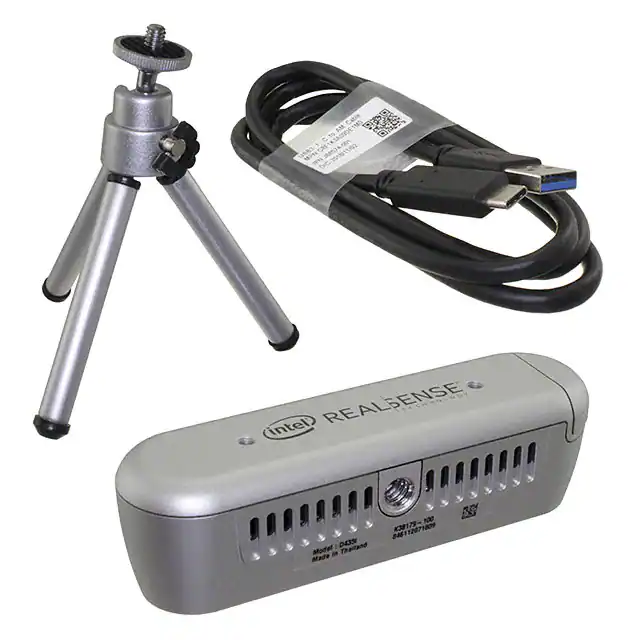


 工商网监
湘ICP备2023018690号
工商网监
湘ICP备2023018690号

