Power Capacitors
Series/Type:
B25835
The following products presented in this data sheet are being withdrawn.
Ordering Code
Substitute Product
B25835M7474K007
B25835M7224K007
B25835M7104K007
Date of
Withdrawal
2014-08-14
2014-08-14
2014-08-14
Deadline Last
Orders
2015-03-31
2015-03-31
2015-03-31
Last
Shipments
2016-09-30
2016-09-30
2016-09-30
© EPCOS AG 2015. Reproduction, publication and dissemination of this publication, enclosures hereto and the
information contained therein without EPCOS' prior express consent is prohibited.
EPCOS AG is a TDK Group Company.
�Ordering Code
B25835M6684K007
B25835M6475K007
B25835M6474K007
B25835M6334K007
B25835M6225K007
B25835M6224K007
B25835M6105K007
B25835M2684K007
B25835M2474K007
B25835M2334K007
B25835M2224K007
B25835M2154K007
B25835M2104K007
B25835M1684K007
B25835M1474K007
B25835M1225K007
B25835M1105K007
B25835M0684K007
B25835M0474K007
B25835M0334K007
B25835M0225K007
B25835M0224K007
B25835M0105K007
B25835M0104K007
Substitute Product
Date of
Withdrawal
2014-08-14
2014-08-14
2014-08-14
2014-08-14
2014-08-14
2014-08-14
2014-08-14
2014-08-14
2014-08-14
2014-08-14
2014-08-14
2014-08-14
2014-08-14
2014-08-14
2014-08-14
2014-08-14
2014-08-14
2014-08-14
2014-08-14
2014-08-14
2014-08-14
2014-08-14
2014-08-14
2014-08-14
Deadline Last
Orders
2015-03-31
2015-03-31
2015-03-31
2015-03-31
2015-03-31
2015-03-31
2015-03-31
2015-03-31
2015-03-31
2015-03-31
2015-03-31
2015-03-31
2015-03-31
2015-03-31
2015-03-31
2015-03-31
2015-03-31
2015-03-31
2015-03-31
2015-03-31
2015-03-31
2015-03-31
2015-03-31
2015-03-31
Last
Shipments
2016-09-30
2016-09-30
2016-09-30
2016-09-30
2016-09-30
2016-09-30
2016-09-30
2016-09-30
2016-09-30
2016-09-30
2016-09-30
2016-09-30
2016-09-30
2016-09-30
2016-09-30
2016-09-30
2016-09-30
2016-09-30
2016-09-30
2016-09-30
2016-09-30
2016-09-30
2016-09-30
2016-09-30
For further information please contact your nearest EPCOS sales office, which will also support
you in selecting a suitable substitute. The addresses of our worldwide sales network are
presented at www.epcos.com/sales.
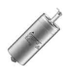
�MKV AC Capacitors
B25835
Damping
Features
■ High dielectric strength
■ High peak-current capability
Applications
■ Especially suitable for snubber circuits
Construction
■
■
■
■
■
■
■
Self-healing
Plastic dielectric
Oil-impregnated tubular windings (no PCB)
Metal-sprayed end faces ensure reliable contacting
Cylindrical aluminum case
1-pole version, ceramic lead-through
Mounting bolts M 8 or M12
Terminals
■ Tab connector 6.3 mm
Mounting
■ If the vibration stress is ≤ 5 g the bolt is used for mounting.
Grounding
■ 1-pole capacitors need not be grounded.
Overpressure disconnector (mechanical)
When the overpressure responds, the capacitor extends by up 8 mm.
So leave sufficient space above the terminals when mounting the capacitor.
Individual data sheets
Individual data sheets contain detailed specification incl. thermal data.
Upon request, these data sheets are available for each capacitor type.
Please read Cautions and warnings and
Important notes at the end of this document.
2
09/05
�MKV AC Capacitors
B25835
Damping
Technical data
Standards
Dielectric dissipation factor
IEC 1071-1/2
EN 61071-1/2
VDE 0560 part 120 and 121
2 · 10 –4
tan δ0
± 10%
Capacitance tolerance
Max. repetitive rate
of voltage rise
(dv/dt)max
Max. non-repetitive rate
of voltage rise
(dv/dt)s
î
--C
IS
--C
Min. operating temperature
Tmin
– 25 °C
Max. operating temperature
Tmax
Climatic data:
+ 85 °C
Average relative humidity
≤ 95%
Failure quota
αFQ(co)
Load duration
tLD(co)
100 000 h
Storage temperature limit
Tstg
– 55 / + 85 °C
300 failures per 109 component hours
IEC climatic category
(IEC 68-1 and 2)
25/085/56
Test data:
AC test voltage between terminals
V TT
1.25 x VR, 50 Hz, 10 s (or DC 1.75 x VR, 10 s)
Insulation resistance
R ins
CR ≤ 1 μF: ≥ 10 000 MΩ
Self-discharge time constant
Dissipation factor (50 Hz)
τ =R ins x C CR > 1 μF: ≥ 10 000 s
tan δ
≤ 3 . 10 –4
Please read Cautions and warnings and
Important notes at the end of this document.
3
09/05
�MKV AC Capacitors
B25835
Damping
Characteristics and ordering codes
CR1)
I max
î
Is
RS
Lself Dimensions Fig. Appr. Ordering code
d×l
weight
20 °C
μF
A
A
A
mΩ
10
10
10
18
18
18
18
90
130
100
150
220
480
1000
220
330
250
370
550
1200
2500
10
10
10
18
18
18
18
150
220
200
280
400
600
1300
380
550
500
700
1000
1500
3300
10
10
18
200
300
660
110
110
110
110
110
110
110
25
25
25
30
30
45
60
× 57
× 57
× 57
× 57
× 57
× 57
× 57
20.0
18.0
27.0
20.0
15.0
12.0
7.6
110
140
190
190
190
190
190
500
750
1600
16.0
15.0
8.4
1
1
1
1
1
1
1
25
25
25
30
30
35
50
× 57
× 70
× 95
× 95
× 95
× 95
× 95
2
1
1
1
1
1
1
40
40
40
50
50
110
190
110 25 × 57
140 25 × 70
140 35 × 70
2
1
1
4
09/05
B25835M6224K007
B25835M6334K007
B25835M6474K007
B25835M6684K007
B25835M6105K007
B25835M6225K007
B25835M6475K007
VTT = AC 1800 V, 10 s
40
50
60
90
90
110
220
v s = 2900 V
1) Other capacitance values upon request
Please read Cautions and warnings and
Important notes at the end of this document.
VTT = AC 1150 V, 10 s
v s = 2400 V
vˆ = 2100 V
VR = AC 1700 V
0.10
0.22
0.47
15.0
11.0
19.0
14.0
10.0
6.6
4.6
v s = 1500 V
vˆ = 1800 V
VR = AC 1400 V
0.10
0.22
0.33
0.47
0.68
1.00
2.20
g
mm
vˆ = 1100 V
VR = AC 900 V
0.22
0.33
0.47
0.68
1.00
2.20
4.70
nH
B25835M0104K007
B25835M0224K007
B25835M0334K007
B25835M0474K007
B25835M0684K007
B25835M0105K007
B25835M0225K007
VTT = AC 2100 V, 10 s
40
50
90
B25835M7104K007
B25835M7224K007
B25835M7474K007
�MKV AC Capacitors
B25835
Damping
Characteristics and ordering codes
CR1)
I max
î
Is
RS
Lself Dimensions Fig. Appr. Ordering code
d×l
weight
20 °C
μF
A
A
A
mΩ
18
18
18
18
750
1100
1600
1100
1900
2700
4000
2800
18
18
18
18
18
18
280
400
600
900
1300
1900
11.0
8.7
7.1
13.0
190
190
190
250
vs = 3600 V
35
40
45
60
× 95
× 95
× 95
× 131
vˆ = 4300 V
VR = AC 3400 V
0.10
0.15
0.22
0.33
0.47
0.68
g
mm
vˆ = 2600 V
VR = AC 2100 V
0.47
0.68
1.00
2.20
nH
700
1000
1500
2300
3300
4800
33.0
24.0
18.0
15.0
12.0
11.0
250
250
250
250
250
250
2
1
1
1
v s = 5800 V
35
35
35
50
50
60
× 131
× 131
× 131
× 131
× 131
× 131
1
1
1
1
1
1
1) Other capacitance values upon request
Please read Cautions and warnings and
Important notes at the end of this document.
110
140
180
440
5
09/05
150
150
150
300
300
440
VTT = AC 2600 V, 10 s
B25835M1474K007
B25835M1684K007
B25835M1105K007
B25835M1225K007
VTT = AC 4300 V, 10 s
B25835M2104K007
B25835M2154K007
B25835M2224K007
B25835M2334K007
B25835M2474K007
B25835M2684K007
�MKV AC Capacitors
B25835
Damping
Tab connector
A 6,3 x 0,8
DIN 46 244
d
l1
l
l2
Dimensional drawing
KLK1408-5
d +0.5
– 0.2
l +1
–2
l1 +1*) l2 max
mm
mm
mm
mm
25
57
8
15
6
6
25
25
25
57
70
95
8
8
8
23
23
23
14
14
14
14
14
14
30
30
57
95
8
8
15
23
6
14
6
14
35
35
70
95
8
8
26
26
14
14
14
14
35
35
95
131
8
8
32
32
20
20
20
20
40
95
8
32
20
20
45
45
57
95
8
8
22
32
10
20
10
20
50
50
95
131
12
12
26
32
14
20
14
20
60
60
57
131
12
12
22
32
10
20
10
20
Creepage Cleardistance ance
mm
mm
8 mm =threaded bolt M 8
12 mm =threaded bolt M12
*)
Mounting parts (included in delivery)
Threaded bolt
Washer
Hex nut
M8
Max. torque
4 Nm
A 8.4 DIN 125-Ms
M 8 DIN 439
M12
10 Nm
A 13 DIN 125-Ms
M12 DIN 439
Please read Cautions and warnings and
Important notes at the end of this document.
6
09/05
�MKV AC Capacitors
B25835
Damping
Cautions and warnings
Safety
■ In case of dents of more than 1 mm depth or any other mechanical damage, capacitors must not
be used at all. This applies also in cases of oil leakage.
■ Electrical or mechanical misapplication of capacitors may be hazardous. Personal injury or prop-
■
■
■
■
■
■
erty damage may result from bursting of the capacitor or from expulsion of oil or melted material
due to mechanical disruption of the capacitor.
Ensure good, effective grounding for capacitor enclosures.
Observe appropriate safety precautions during operation (self-recharging phenomena and the
high energy contained in capacitors).
Handle capacitors carefully, because they may still be charged even after disconnection.
The terminals of capacitors, connected bus bars and cables as well as other devices may also
be energized.
Follow good engineering practice.
Failure to follow cautions may result, worst case, in premature failures, bursting and fire.
Thermal load
After installation of the capacitor it is necessary to verify that maximum hot-spot temperature is not
exceeded at extreme service conditions (see www.epcos.com/thermal_design).
Mechanical protection
The capacitor has to be installed in a way that mechanical damages and dents in the aluminum can
are avoided.
Storage and operating conditions
Do not use or store capacitors in corrosive atmosphere especially where chloride gas, sulfide gas,
acid, alkali, salt or the like are present. In dusty environments, regular maintenance and cleaning
especially of the terminals is required to avoid conductive path between phases and/or phases and
ground.
Overpressure disconnector
To ensure full functionality of an overpressure disconnector, the following must be observed:
■ The elastic elements must not be hindered, i.e.
– connecting lines must be flexible leads (cables),
– there must be sufficient space (minimum 12 mm) above the connections for expansion of the
overpressure disconnector,
– folding crimps must not be retained by clamps.
■ Stress parameters of the capacitor must be within the IEC61071 specification.
Service life expectancy
Electrical components do not have an unlimited service life expectancy; this applies to self-healing
capacitors too. The maximum service life expectancy may vary depending on the application the
capacitor is used in.
7
09/05
�Important notes
The following applies to all products named in this publication:
1. Some parts of this publication contain statements about the suitability of our products for certain
areas of application. These statements are based on our knowledge of typical requirements that are
often placed on our products in the areas of application concerned. We nevertheless expressly point
out that such statements cannot be regarded as binding statements about the suitability of our
products for a particular customer application. As a rule we are either unfamiliar with individual
customer applications or less familiar with them than the customers themselves. For these reasons, it is
always ultimately incumbent on the customer to check and decide whether a product with the properties
described in the product specification is suitable for use in a particular customer application.
2. We also point out that in individual cases, a malfunction of electronic components or failure
before the end of their usual service life cannot be completely ruled out in the current state of the
art, even if they are operated as specified. In customer applications requiring a very high level of
operational safety and especially in customer applications in which the malfunction or failure of an
electronic component could endanger human life or health (e.g. in accident prevention or life-saving
systems), it must therefore be ensured by means of suitable design of the customer application or other
action taken by the customer (e.g. installation of protective circuitry or redundancy) that no injury or
damage is sustained by third parties in the event of malfunction or failure of an electronic component.
3. The warnings, cautions and product-specific notes must be observed.
4. In order to satisfy certain technical requirements, some of the products described in this publication
may contain substances subject to restrictions in certain jurisdictions (e.g. because they are
classed as hazardous). Useful information on this will be found in our Material Data Sheets on the
Internet (www.tdk-electronics.tdk.com/material). Should you have any more detailed questions, please
contact our sales offices.
5. We constantly strive to improve our products. Consequently, the products described in this
publication may change from time to time. The same is true of the corresponding product
specifications. Please check therefore to what extent product descriptions and specifications contained
in this publication are still applicable before or when you place an order.
We also reserve the right to discontinue production and delivery of products. Consequently, we
cannot guarantee that all products named in this publication will always be available. The
aforementioned does not apply in the case of individual agreements deviating from the foregoing for
customer-specific products.
6. Unless otherwise agreed in individual contracts, all orders are subject to our General Terms and
Conditions of Supply.
7. Our manufacturing sites serving the automotive business apply the IATF 16949 standard. The
IATF certifications confirm our compliance with requirements regarding the quality management system
in the automotive industry. Referring to customer requirements and customer specific requirements
(“CSR”) TDK always has and will continue to have the policy of respecting individual agreements. Even
if IATF 16949 may appear to support the acceptance of unilateral requirements, we hereby like to
emphasize that only requirements mutually agreed upon can and will be implemented in our
Quality Management System. For clarification purposes we like to point out that obligations from IATF
16949 shall only become legally binding if individually agreed upon.
8. The trade names EPCOS, CeraCharge, CeraDiode, CeraLink, CeraPad, CeraPlas, CSMP, CTVS,
DeltaCap, DigiSiMic, ExoCore, FilterCap, FormFit, LeaXield, MiniBlue, MiniCell, MKD, MKK, MotorCap,
PCC, PhaseCap, PhaseCube, PhaseMod, PhiCap, PowerHap, PQSine, PQvar, SIFERRIT, SIFI,
SIKOREL, SilverCap, SIMDAD, SiMic, SIMID, SineFormer, SIOV, ThermoFuse, WindCap are
trademarks registered or pending in Europe and in other countries. Further information will be found
on the Internet at www.tdk-electronics.tdk.com/trademarks.
Release 2018-10
8
09/05
�


 工商网监
湘ICP备2023018690号
工商网监
湘ICP备2023018690号
