NTC thermistors for
temperature measurement
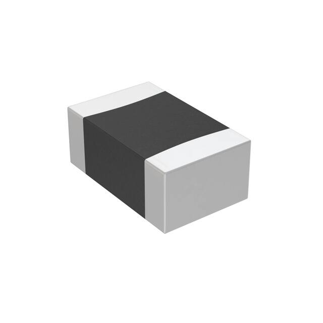
SMD NTC thermistors,
EIA case size 0805 (2012), automotive series
Series/Type:
B574**V5
Date:
February 2019
© TDK Electronics AG 2019. Reproduction, publication and dissemination of this publication, enclosures hereto
and the information contained therein without TDK Electronics' prior express consent is prohibited.
�Temperature measurement and compensation
B574**V5
SMD NTC thermistors, case size 0805 (2012)
Applications
Temperature measurement and compensation
Features
Qualification based on AEC-Q200 Rev-D
Multilayer SMD NTC with inner electrodes
Nickel barrier termination
For temperature measurement up to 150 °C
Excellent long-term aging stability in high
temperature and high humidity environment
High mechanical robustness
Short response time
100% Pb free
UL approval (E69802)
Automotive series
Dimensional drawing
Dimensions in mm
Approx. weight 13 mg
Options
Alternative resistance ratings, resistance
tolerances and B value tolerances available on
request.
Delivery mode
Cardboard tape, 180-mm reel
General technical data
Operating temperature range
Max. power
Resistance tolerance
Rated temperature
Dissipation factor
Thermal cooling time constant
Heat capacity
Top
(at 25 °C, on PCB) P251)
∆RR/RR
TR
(on PCB)
δth1)
(on PCB)
τc1)
Cth1)
1) Depends on mounting situation
Please read Cautions and warnings and
Important notes at the end of this document.
Page 2 of 27
�40 ... 150
210
±3, ±5
25
approx. 3.5
approx. 10
approx. 35
°C
mW
%
°C
mW/K
s
mJ/K
�Temperature measurement and compensation
B574**V5
SMD NTC thermistors, case size 0805 (2012)
Automotive series
Electrical specification and ordering codes
R25
Ω
4.7 k
4.7 k
10 k
10 k
10 k
22 k
33 k
47 k
100 k
∆RR/RR
%
±3, ±5
±3, ±5
±3, ±5
±3, ±5
±3, ±5
±5
±3, ±5
±3, ±5
±3, ±5
No. of R/T
characteristic
8500
8507
8500
8502
8507
8507
8502
8502
8507
B25/50
K
3590
4386
3590
3940
4386
4386
3940
3940
4386
B25/85
K
3635
4455
3635
3980
4455
4455
3980
3980
4455
+ = Resistance tolerance
H = ±3%
J = ±5%
Please read Cautions and warnings and
Important notes at the end of this document.
Page 3 of 27
B25/100
K
3650 ±3%
4480 ±3%
3650 ±3%
4000 ±3%
4480 ±3%
4480 ±3%
4000 ±3%
4000 ±3%
4480 ±3%
Ordering code
B57442V5472+062
B57452V5472+062
B57442V5103+062
B57451V5103+062
B57452V5103+062
B57452V5223J062
B57451V5333+062
B57451V5473+062
B57452V5104+062
�Temperature measurement and compensation
SMD NTC thermistors, case size 0805 (2012)
B574**V5
Automotive series
Reliability data
Tests of SMD NTC thermistors are based on AEC-Q200 Rev-D. The parts are mounted on
standardized PCB.
Test
Pre- and
post-stress
electrical test
High temperature
exposure
(storage)
Temperature
cycling
Standard
Test conditions
Resistance at: 25 °C and 100 °C
Physical
dimensions
Test temperature: 150 °C
Duration: 1000 h
Unpowered
JESD22,
Lower test temperature: �40 °C
method JA-104 Upper test temperature: 150 °C
Number of cycles: 1000
Transfer time: < 10 s
Dwell time: 15 min
Air � Air
MIL-STD-202, Test temperature: 85 °C
method 103
Rel. humidity of air: 85%
Duration: 1000 h
Test voltage: VNTC = 0.3 V DC
MIL-STD-202, Test temperature: 150 °C
method 108
Pmax = 0.35 mW
Duration: 1000 h
MIL-STD-883E, Visual inspection
method 2009
JESD22,
Measured with calipers
method JB-100
Resistance to
solvents
MIL-STD-202,
method 215
Mechanical shock
MIL-STD-202,
method 213
Vibration
MIL-STD-202,
method 204
Resistance to
soldering heat
MIL-STD-202,
method 210
Biased humidity
Operational life
External visual
∆R25/R25 Remarks
(typical)
MIL-STD-202,
method 108
Please read Cautions and warnings and
Important notes at the end of this document.
Not applicable for SMD thermistors
(component has no marking, color
coding or coating)
Peak value: 1500 g
Half sine
Condition F
Acceleration: 5 g
Sweep time: 20 min
Frequency range: 10 ... 2000 Hz
3 × 12 cycles
Dip: 260 °C; 10 s
1 heat cycle
Page 4 of 27
< 5%
< 5%
< 5%
< 5%
Within the
specified
values
< 5%
< 5%
< 3%
�Temperature measurement and compensation
B574**V5
SMD NTC thermistors, case size 0805 (2012)
Automotive series
Test
Standard
ESD
AEC-Q200-002, Discharge capacitance: 150 pF
method -002
Discharge resistance: 2 kΩ
Charging voltage: 6 kV
Contact discharge
2 pulses in each polarity
J-STD-002
a) Dip: 235 °C; 5 s:
aging 4 h @ 155 °C
b) Dip: 215 °C; 5 s:
steam aging 8 h @ 92 °C
c) Dip: 260 °C; 7 s:
steam aging 8 h @ 92 °C
R(25 °C), R(100 °C), B(25/100)
∆R25/R25 Remarks
(typical)
< 5%
Solderability
Electrical
characterization
Flammability
Board flex
Terminal strength
Resistance drift
after soldering
Test conditions
Not applicable for SMD thermistors
(component is not coated or
encapsulated with plastic materials)
AEC-Q200-005, Max. bending: 2 mm
method -005
Duration @ max. bending: 60 s
AEC-Q200-006, Max. F: 17.7 N
method -006
Reflow soldering profile
Wave soldering profile
95% of
termination
wetted
Within the
specified
values
UL-94,
V-0 or V-1
Please read Cautions and warnings and
Important notes at the end of this document.
Page 5 of 27
< 5%
< 5%
< 1%
�Temperature measurement and compensation
B574**V5
SMD NTC thermistors, case size 0805 (2012)
Automotive series
R/T characteristics
R/T No.
T (°C)
8500
8502
8507
B25/100 = 3650 K
B25/100 = 4000 K
B25/100 = 4480 K
RT/R25
α (%/K) RT/R25
α (%/K) RT/R25
α (%/K)
�55.0
�50.0
�45.0
�40.0
�35.0
63.917
45.889
33.344
24.504
18.201
6.8
6.5
6.3
6.1
5.8
96.158
66.892
47.127
33.606
24.243
7.4
7.1
6.9
6.6
6.4
�30.0
�25.0
�20.0
�15.0
�10.0
13.657
10.347
7.9114
6.1019
4.7454
5.6
5.5
5.3
5.1
4.9
17.681
13.032
9.702
7.2923
5.5314
6.2
6.0
5.8
5.6
5.4
23.213
16.686
12.115
8.8803
6.5692
6.7
6.5
6.3
6.1
5.9
�5.0
0.0
5.0
10.0
15.0
3.7198
2.938
2.3372
1.8722
1.5096
4.8
4.6
4.5
4.4
4.2
4.2325
3.2657
2.54
1.9907
1.5716
5.3
5.1
4.9
4.8
4.7
4.9025
3.6896
2.7994
2.1406
1.6492
5.8
5.6
5.4
5.3
5.1
20.0
25.0
30.0
35.0
40.0
1.2249
1.0000
0.82111
0.67798
0.56279
4.1
4.0
3.9
3.8
3.7
1.2494
1.0000
0.80552
0.65288
0.53229
4.5
4.4
4.3
4.1
4.0
1.2798
1.0000
0.78663
0.62277
0.4961
5.0
4.9
4.7
4.6
4.5
45.0
50.0
55.0
60.0
65.0
0.46958
0.39374
0.33171
0.28073
0.23863
3.6
3.5
3.4
3.3
3.2
0.43645
0.35981
0.29819
0.24837
0.20787
3.9
3.8
3.7
3.6
3.5
0.39757
0.32044
0.2597
0.21161
0.17331
4.4
4.3
4.1
4.0
3.9
70.0
75.0
80.0
85.0
90.0
0.2037
0.17459
0.15022
0.12975
0.11247
3.1
3.0
3.0
2.9
2.8
0.17479
0.14763
0.12523
0.10667
0.091227
3.4
3.3
3.2
3.2
3.1
0.14265
0.11799
0.098035
0.081823
0.068589
3.8
3.8
3.7
3.6
3.5
95.0
100.0
105.0
110.0
115.0
0.097838
0.085396
0.074781
0.065691
0.057883
2.8
2.7
2.6
2.6
2.5
0.078319
0.067488
0.058363
0.050647
0.044098
3.0
2.9
2.9
2.8
2.7
0.057735
0.048796
0.041403
0.035263
0.030143
3.4
3.3
3.2
3.2
3.1
120.0
125.0
130.0
135.0
140.0
0.051153
0.045335
0.040289
0.0359
0.032071
2.4
2.4
2.3
2.3
2.2
0.03852
0.033752
0.029663
0.026146
0.023111
2.7
2.6
2.6
2.5
2.4
0.025858
0.022258
0.019223
0.016655
0.014476
3.0
3.0
2.9
2.8
2.8
145.0
150.0
0.028723
0.025786
2.2
2.1
0.020484
0.018203
2.4
2.3
0.012619
0.011033
2.7
2.7
Please read Cautions and warnings and
Important notes at the end of this document.
Page 6 of 27
142.71
96.913
66.637
46.366
32.629
7.9
7.6
7.4
7.1
6.9
�Temperature measurement and compensation
B574**V5
SMD NTC thermistors, case size 0805 (2012)
Automotive series
Taping and packing
1
Taping of SMD NTC thermistors
Tape and reel packing according to IEC 60286-3.
Tape material: Cardboard or blister, tape width 8 ±0.30 mm
2
Reel packing
Dimensions in mm
8-mm tape
180-mm reel
330-mm reel
A
180 +0/�3
330 +0/�2.0
W1
8.4 +1.5/�0
8.4 +1.5/�0
W2
14.4 max.
14.4 max.
Leader, trailer
Please read Cautions and warnings and
Important notes at the end of this document.
Page 7 of 27
�Temperature measurement and compensation
B574**V5
SMD NTC thermistors, case size 0805 (2012)
Automotive series
Packing units for discrete chip
Case size
Chip thickness
inch/mm
0402/1005
0603/1608
0805/2012
1206/3216
3
th
0.5 mm
0.8 mm
0.8 mm
1.2 mm
0.8 mm
1.2 mm
Cardboard tape Blister tape
W
8 mm
8 mm
�
�
�
�
W
�
8 mm
8 mm
8 mm
8 mm
8 mm
∅ 180-mm reel ∅ 330-mm reel
pcs.
10000
4000
2000/ 4000
3000
2000
4000
pcs.
50000
16000
16000
12000
12000
12000
Packing codes
The last two digits of the complete ordering code state the packing mode:
Last two digits
60
SMD
Cardboard tape
180-mm reel packing
62
SMD
Blister tape
180-mm reel packing
70
SMD
Cardboard tape
330-mm reel packing
72
SMD
Blister tape
330-mm reel packing
Please read Cautions and warnings and
Important notes at the end of this document.
Page 8 of 27
�Temperature measurement and compensation
B574**V5
SMD NTC thermistors, case size 0805 (2012)
4
Automotive series
Taping of radial leaded NTC thermistors
Dimensions and tolerances
Lead spacing F = 2.5 mm and 5.0 mm (taping to IEC 60286-2)
Dimensions (mm)
w
th
d
P0
P1
F
∆h
∆p
W
W0
W1
W2
H
H0
H1
D0
t
L
L1
Lead
spacing
2.5 mm
11.0
5.0
0.5/0.6
12.7
5.1
2.5
0
0
18.0
5.5
9.0
3.0
18.0
16.0
32.2
4.0
0.9
11.0
4.0
Lead
spacing
5 mm
11.5
6.0
0.5/0.6
12.7
3.85
5.0
0
0
18.0
5.5
9.0
3.0
18.0
16.0
32.2
4.0
0.9
11.0
4.0
Please read Cautions and warnings and
Important notes at the end of this document.
Tolerance of
lead spacing
2.5/5 mm
max.
max.
±0.05
±0.3
±0.7
+0.6/�0.1
±2.0
±1.3
±0.5
min.
+0.75/�0.5
max.
+2.0/�0
±0.5
max.
±0.2
max.
max.
max.
Remarks
±1 mm / 20 sprocket holes
measured at top of component body
peel-off force ≥5 N
without wires
Page 9 of 27
�Temperature measurement and compensation
B574**V5
SMD NTC thermistors, case size 0805 (2012)
Automotive series
Types of packing
Ammo packing
Ammo
type
x
y
z
I
80
240
210
Packing unit: 1000 - 2000 pcs./reel
Reel packing
Packing unit: 1000 - 2000 pcs./reel
Reel dimensions (in mm)
Reel type
d
f
n
w
I
360 max.
31 ±1
approx. 45
54 max.
Please read Cautions and warnings and
Important notes at the end of this document.
Page 10 of 27
�Temperature measurement and compensation
SMD NTC thermistors, case size 0805 (2012)
B574**V5
Automotive series
Cassette packing
Packing unit: 1000 - 2000 pcs./cassette
Bulk packing
The components are packed in cardboard boxes, the size of which depends on the order quantity.
Please read Cautions and warnings and
Important notes at the end of this document.
Page 11 of 27
�Temperature measurement and compensation
B574**V5
SMD NTC thermistors, case size 0805 (2012)
5
Automotive series
Packing codes
The last two digits of the complete ordering code state the packing mode:
Last two digits
00, 01, 02, 03,04,
05, 06, 07, 08
�
Bulk
�
40, 41
�
Bulk
�
45
�
Bulk
�
50
Radial leads, kinked
Cardboard tape
Cassette packing
51
Radial leads, kinked
Cardboard tape
360-mm reel packing
52
Radial leads, straight
Cardboard tape
Cassette packing
53
Radial leads, straight
Cardboard tape
360-mm reel packing
54
Radial leads, kinked
Cardboard tape
AMMO packing
55
Radial leads, straight
Cardboard tape
AMMO packing
(If no packing code is indicated, this corresponds to 40)
Example 1:
B57164K0102J000
B57164K0102J052
Bulk
Cardboard tape, cassette packing
Example 2:
B57881S0103F002
B57881S0103F251
Bulk
Cardboard tape, reel packing
Please read Cautions and warnings and
Important notes at the end of this document.
Page 12 of 27
�Temperature measurement and compensation
B574**V5
SMD NTC thermistors, case size 0805 (2012)
Automotive series
Mounting instructions
1
Soldering
1.1
Leaded NTC thermistors
Leaded thermistors comply with the solderability requirements specified by CECC.
When soldering, care must be taken that the NTC thermistors are not damaged by excessive
heat. The following maximum temperatures, maximum time spans and minimum distances have
to be observed:
Dip soldering
Iron soldering
Bath temperature
max. 260 °C
max. 360 °C
Soldering time
max. 4 s
max. 2 s
Distance from thermistor
min. 6 mm
min. 6 mm
Under more severe soldering conditions the resistance may change.
1.1.1
Wave soldering
Temperature characteristic at component terminal with dual wave soldering
Please read Cautions and warnings and
Important notes at the end of this document.
Page 13 of 27
�Temperature measurement and compensation
B574**V5
SMD NTC thermistors, case size 0805 (2012)
1.2
Automotive series
Leadless NTC thermistors
In case of NTC thermistors without leads, soldering is restricted to devices which are provided
with a solderable metallization. The temperature shock caused by the application of hot solder
may produce fine cracks in the ceramic, resulting in changes in resistance.
To prevent leaching of the metallization, solder with silver additives or with a low tin content
should be used. In addition, soldering methods should be employed which permit short soldering
times.
1.3
SMD NTC thermistors
SMD NTC thermistors can be provided with a nickel barrier termination or on special request with
silver-palladium termination. The use of no-clean solder products is recommended. In any case
mild, non-activated fluxes should be used. Flux residues after soldering should be minimized.
SMD NTCs with AgPd termination are not approved for lead-free soldering.
Nickel barrier termination
Figure 1
SMD NTC thermistors, structure of nickel
barrier termination
The nickel barrier layer of the silver/nickel/tin termination (see figure 1) prevents leaching of the
silver base metallization layer. This allows great flexibility in the selection of soldering parameters.
The tin prevents the nickel layer from oxidizing and thus ensures better wetting by the solder. The
nickel barrier termination is tested for all commonly-used soldering methods according to
IEC 60068-2-58. Insufficient preheating may cause ceramic cracks. Rapid cooling by dipping in
solvent is not recommended.
The following test and process conditions apply for nickel barrier termination.
Please read Cautions and warnings and
Important notes at the end of this document.
Page 14 of 27
�Temperature measurement and compensation
SMD NTC thermistors, case size 0805 (2012)
1.3.1
B574**V5
Automotive series
Solderability (test to IEC 60068-2-58)
Preconditioning: Immersion into flux F-SW 32.
Evaluation criterion: Wetting of soldering areas ≥95%.
Solder
Bath temperature (°C)
Dwell time (s)
SnPb 60/40
215 ±3
3 ±0.3
SnAg (3.0 ... 4.0), Cu (0.5 ... 0.9)
245 ±3
3 ±0.3
1.3.2
Resistance to soldering heat (test to IEC 60068-2-58)
Preconditioning: Immersion into flux F-SW 32.
Evaluation criterion: Leaching of side edges ≤1/3.
Solder
Bath temperature (°C)
Dwell time (s)
SnPb 60/40
260 ±5
10 ±1
SnAg (3.0 ... 4.0), Cu (0.5 ... 0.9)
260 ±5
10 ±1
1.3.3
Reflow soldering
Temperature ranges for reflow soldering acc. to IEC 60068-2-58 recommendations.
Please read Cautions and warnings and
Important notes at the end of this document.
Page 15 of 27
�Temperature measurement and compensation
B574**V5
SMD NTC thermistors, case size 0805 (2012)
Automotive series
Profile feature
Preheat and soak
- Temperature min
- Temperature max
- Time
Sn-Pb eutectic assembly
Pb-free assembly
Tsmin
Tsmax
tsmin to tsmax
100 °C
150 °C
60 ... 120 s
150 °C
200 °C
60 ... 120 s
Average ramp-up rate
Tsmax to Tp
3 °C/ s max.
3 °C/ s max.
Liquidous temperature
Time at liquidous
TL
tL
183 °C
40 ... 150 s
217 °C
40 ... 150 s
Peak package body temperature
Tp
215 °C ... 260 °C1)
235 °C ... 260 °C
Time above (TP �5 °C)
tp
10 ... 40 s
10 ... 40 s
Average ramp-down rate
Tp to Tsmax
6 °C/ s max.
6 °C/ s max.
max. 8 minutes
max. 8 minutes
Time 25 °C to peak temperature
1) Depending on package thickness.
Notes:
All temperatures refer to topside of the package, measured on the package body
surface.
Number of reflow cycles: 3
Iron soldering should be avoided, hot air methods are recommended for repair
purposes.
Solder joint profiles for silver/nickel/tin terminations
Please read Cautions and warnings and
Important notes at the end of this document.
Page 16 of 27
�Temperature measurement and compensation
SMD NTC thermistors, case size 0805 (2012)
1.3.4
B574**V5
Automotive series
Recommended geometry of solder pads
Recommended maximum dimensions (mm)
Case size
inch/mm
A
B
C
0402/1005
0.6
0.6
1.7
0603/1608
1.0
1.0
3.0
0805/2012
1.3
1.2
3.4
1206/3216
1.8
1.2
4.5
2
Conductive adhesion
An alternative to soldering for silver-palladium terminated components is the gluing of thermistors
with conductive adhesives. The benefit of this method is that it involves no thermal stress. The
adhesives used must be chemically inert.
3
Clamp contacting
Pressure contacting by means of clamps is particularly suitable for applications involving frequent
switching and high turn-on powers.
4
Robustness of terminations (leaded types)
The leads meet the requirements of IEC 60068-2-21. They may not be bent closer than 4 mm
from the solder joint on the thermistor body or from the point at which they leave the feedthroughs. During bending, any mechanical stress at the outlet of the leads must be removed. The
bending radius should be at least 0.75 mm.
Please read Cautions and warnings and
Important notes at the end of this document.
Page 17 of 27
�Temperature measurement and compensation
SMD NTC thermistors, case size 0805 (2012)
Tensile strength:
B574**V5
Automotive series
Test Ua1:
Value of applied force for Ua1 test:
Diameter (d) of
Force with tolerance of ±10%
corresponding round leads
∅ ≤ 0.25 mm
1.0 N
0.25 < ∅ ≤ 0.35 mm
2.5 N
0.35 < ∅ ≤ 0.50 mm
5.0 N
0.50 < ∅ ≤ 0.80 mm
10.0 N
Bending strength: Test Ub:
Two 90°-bends in opposite directions
Value of applied force for Ub test:
Diameter (d) of
Force with tolerance of ±10%
corresponding round leads
∅ ≤ 0.25 mm
0.5 N
0.25 < ∅ ≤ 0.35 mm
1.25 N
0.35 < ∅ ≤ 0.50 mm
2.5 N
0.50 < ∅ ≤ 0.80 mm
5N
Torsional strength: Test Uc: severity 2
The lead is bent by 90° at a distance of 6 to 6.5 mm from the thermistor body.
The bending radius of the leads should be approx. 0.75 mm. Two torsions of
180° each (severity 2).
When subjecting leads to mechanical stress, the following should be observed:
Tensile stress on leads
During mounting and operation tensile forces on the leads are to be avoided.
Bending of leads
Bending of the leads directly on the thermistor body is not permissible.
A lead may be bent at a minimum distance of twice the wire's diameter +4 mm from the solder
joint on the thermistor body. During bending the wire must be mechanically relieved at its outlet.
The bending radius should be at least 0.75 mm.
Please read Cautions and warnings and
Important notes at the end of this document.
Page 18 of 27
�Temperature measurement and compensation
SMD NTC thermistors, case size 0805 (2012)
5
B574**V5
Automotive series
Sealing and potting
Sealing or potting processes can affect the reliability of the component.
When thermistors are sealed, potted or overmolded, there must be no mechanical stress caused
by thermal expansion during the production process (curing / overmolding process) and during
later operation. The upper category temperature of the thermistor must not be exceeded. Ensure
that the materials used (sealing / potting compound and plastic material) are chemically neutral.
As thermistors are temperature sensitive components it should be considered that molding can affect the thermal surrounding and may influence e.g. the response time.
Extensive testing is encouraged in order to determine whether overmolding or potting influences
the functionality and/ or reliability of the component.
6
Cleaning
Cleaning processes can affect the reliability of the component.
If cleaning is necessary, mild cleaning agents are recommended. Cleaning agents based on water are not allowed. Washing processes may damage the product due to the possible static or
cyclic mechanical loads (e.g. ultrasonic cleaning). They may cause cracks which might lead to reduced reliability and/ or lifetime.
7
Storage
In order to maintain their solderability, thermistors must be stored in a non-corrosive atmosphere.
Humidity, temperature and container materials are critical factors.
Do not store SMDs where they are exposed to heat or direct sunlight. Otherwise, the packing material may be deformed or SMDs may stick together, causing problems during mounting. After
opening the factory seals, such as polyvinyl-sealed packages, use the SMDs as soon as possible.
The components should be left in the original packing. Touching the metallization of unsoldered
thermistors may change their soldering properties.
Storage temperature:
�25 °C up to 45 °C
Relative humidity (without condensation):
≤75% annual mean