SIOV metal oxide varistors
Leaded varistors, StandarD series
Series/Type:
B722*
Date:
March 2018
© EPCOS AG 2018. Reproduction, publication and dissemination of this publication, enclosures hereto and the
information contained therein without EPCOS' prior express consent is prohibited.
EPCOS AG is a TDK Group Company.
�Leaded varistors
B722*
StandarD series
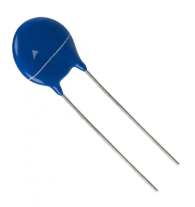
Construction
Round varistor element, leaded
Coating: epoxy resin, flame-retardant to UL 94 V-0
Terminals: tinned wire
Features
Wide operating voltage range 11 … 1100 VRMS
High surge current ratings up to 8 kA
No derating up to 105 °C ambient temperature
PSpice models
Approvals
UL
CSA (all types ≥ K115)
VDE
CQC S05/07 (K11 … K460), S10/S14 (K11 … K680), S20 (K11 … K1000)
IEC
Delivery mode
Bulk (standard), taped versions on reel or in Ammo pack upon request.
For further details refer to chapter "Taping, packaging and lead configuration" for leaded
varistors.
Options
S10* types with lead spacing 5.0 mm and S20* types with lead spacing 7.5 mm are also
available on request.
General technical data
Climatic category
Operating temperature
Storage temperature
Electric strength
Insulation resistance
Please read Cautions and warnings and
Important notes at the end of this document.
to IEC 60068-1
to IEC 61051
to IEC 61051
to IEC 61051
Page 2 of 47
40/105/56
�40 ... +105
�40 ... +125
≥ 2.5
≥ 100
°C
°C
kVRMS
MΩ
�Leaded varistors
B722*
StandarD series
Electrical specifications and ordering codes
Maximum ratings (TA = 105 °C)
Ordering code
VRMS = 11 V
B72205S0110K101
B72207S0110K101
B72210S0110K101
B72214S0110K101
B72220S0110K101
VRMS = 14 V
B72205S0140K101
B72207S0140K101
B72210S0140K101
B72214S0140K101
B72220S0140K101
VRMS = 17 V
B72205S0170K101
B72207S0170K101
B72210S0170K101
B72214S0170K101
B72220S0170K101
VRMS = 20 V
B72205S0200K101
B72207S0200K101
B72210S0200K101
B72214S0200K101
B72220S0200K101
VRMS = 25 V
B72205S0250K101
B72207S0250K101
B72210S0250K101
B72214S0250K101
B72220S0250K101
VRMS = 30 V
B72205S0300K101
B72207S0300K101
B72210S0300K101
B72214S0300K101
B72220S0300K101
Type
(untaped)
SIOV-
In 1)
Wmax
(8/20 µs) (2 ms)
15 times
A
J
Pmax
V
imax
(8/20 µs)
1 time
A
VRMS
VDC
V
W
S05K11
S07K11
S10K11
S14K11
S20K11
11
11
11
11
11
14
14
14
14
14
100
250
500
1000
2000
50
100
250
500
1000
0.3
0.8
1.7
3.2
10.0
0.01
0.02
0.05
0.10
0.20
S05K14
S07K14
S10K14
S14K14
S20K14
14
14
14
14
14
18
182)
182)
182)
182)
100
250
500
1000
2000
50
100
250
500
1000
0.4
0.9
2.0
4.0
12.0
0.01
0.02
0.05
0.10
0.20
S05K17
S07K17
S10K17
S14K17
S20K17
17
17
17
17
17
22
22
22
22
22
100
250
500
1000
2000
50
100
250
500
1000
0.5
1.1
2.5
5.0
14.0
0.01
0.02
0.05
0.10
0.20
S05K20
S07K20
S10K20
S14K20
S20K20
20
20
20
20
20
26
26
26
26
26
100
250
500
1000
2000
50
100
250
500
1000
0.6
1.3
3.1
6.0
18.0
0.01
0.02
0.05
0.10
0.20
S05K25
S07K25
S10K25
S14K25
S20K25
25
25
25
25
25
31
31
31
31
31
100
250
500
1000
2000
50
100
250
500
1000
0.7
1.6
3.7
7.0
22.0
0.01
0.02
0.05
0.10
0.20
S05K30
S07K30
S10K30
S14K30
S20K30
30
30
30
30
30
38
38
38
38
38
100
250
500
1000
2000
50
100
250
500
1000
0.9
2.0
4.4
9.0
26.0
0.01
0.02
0.05
0.10
0.20
1) Note: Nominal discharge current In according to UL 1449, 4th edition.
2) Jump-start strength (max. 24 V, 5 minutes)
Please read Cautions and warnings and
Important notes at the end of this document.
Page 3 of 47
�Leaded varistors
B722*
StandarD series
Characteristics (TA = 25 °C)
Ordering code
VRMS = 11 V
B72205S0110K101
B72207S0110K101
B72210S0110K101
B72214S0110K101
B72220S0110K101
VRMS = 14 V
B72205S0140K101
B72207S0140K101
B72210S0140K101
B72214S0140K101
B72220S0140K101
VRMS = 17 V
B72205S0170K101
B72207S0170K101
B72210S0170K101
B72214S0170K101
B72220S0170K101
VRMS = 20 V
B72205S0200K101
B72207S0200K101
B72210S0200K101
B72214S0200K101
B72220S0200K101
VRMS = 25 V
B72205S0250K101
B72207S0250K101
B72210S0250K101
B72214S0250K101
B72220S0250K101
VRMS = 30 V
B72205S0300K101
B72207S0300K101
B72210S0300K101
B72214S0300K101
B72220S0300K101
Vv
(1 mA)
V
∆Vv
(1 mA)
%
vc,max
(ic)
V
ic
A
Ctyp
(1 kHz)
pF
18
18
18
18
18
±10
±10
±10
±10
±10
36
36
36
36
36
1.0
2.5
5.0
10.0
20.0
1750
2750
6250
12100
23000
22
22
22
22
22
±10
±10
±10
±10
±10
43
43
43
43
43
1.0
2.5
5.0
10.0
20.0
1450
2300
5200
9950
19000
27
27
27
27
27
±10
±10
±10
±10
±10
53
53
53
53
53
1.0
2.5
5.0
10.0
20.0
1200
1900
4350
8200
15600
33
33
33
33
33
±10
±10
±10
±10
±10
65
65
65
65
65
1.0
2.5
5.0
10.0
20.0
980
1600
3650
6800
13000
39
39
39
39
39
±10
±10
±10
±10
±10
77
77
77
77
77
1.0
2.5
5.0
10.0
20.0
850
1400
3200
5850
11100
47
47
47
47
47
±10
±10
±10
±10
±10
93
93
93
93
93
1.0
2.5
5.0
10.0
20.0
720
1200
2750
4950
9350
Please read Cautions and warnings and
Important notes at the end of this document.
Page 4 of 47
�Leaded varistors
B722*
StandarD series
Electrical specifications and ordering codes
Maximum ratings (TA = 105 °C)
Ordering code
Type
(untaped)
SIOV-
VRMS
VDC
V
V
imax
(8/20 µs)
1 time
A
In 1)
Wmax
(8/20 µs) (2 ms)
15 times
A
J
VRMS = 35 V
B72205S0350K101
S05K35
35
45
100
50
B72207S0350K101
S07K35
35
45
250
100
B72210S0350K101
S10K35
35
45
500
250
B72214S0350K101
S14K35
35
45
1000
500
B72220S0350K101
S20K35
35
45
2000
1000
VRMS = 40 V
B72205S0400K101
S05K40
40
56
100
50
B72207S0400K101
S07K40
40
56
250
100
B72210S0400K101
S10K40
40
56
500
250
B72214S0400K101
S14K40
40
56
1000
500
B72220S0400K101
S20K40
40
56
2000
1000
VRMS = 50 V
B72205S0500K101
S05K50
50
65
400
150
B72207S0500K101
S07K50
50
65
1200
500
B72210S0500K101
S10K50
50
65
2500
1500
B72214S0500K101
S14K50
50
65
4500
3000
B72220S0500K101
S20K50
50
65
6500
3000
VRMS = 60 V
B72205S0600K101
S05K60
60
85
400
150
B72207S0600K101
S07K60
60
85
1200
500
B72210S0600K101
S10K60
60
85
2500
1500
B72214S0600K101
S14K60
60
85
4500
3000
B72220S0600K101
S20K60
60
85
6500
3000
VRMS = 75 V
B72205S0750K101
S05K75
75
100
400
150
B72207S0750K101
S07K75
75
100
1200
500
B72210S0750K101
S10K75
75
100
2500
1500
B72214S0750K101
S14K75
75
100
4500
3000
B72220S0750K101
S20K75
75
100
6500
3000
VRMS = 95 V
B72205S0950K101
S05K95
95
125
400
150
B72207S0950K101
S07K95
95
125
1200
500
B72210S0950K101
S10K95
95
125
2500
1500
B72214S0950K101
S14K95
95
125
4500
3000
B72220S0950K101
S20K95
95
125
6500
3000
1)
Note: Nominal discharge current In according to UL 1449, 4thedition.
Please read Cautions and warnings and
Important notes at the end of this document.
Page 5 of 47
Pmax
W
1.1
2.5
5.4
10.0
33.0
0.01
0.02
0.05
0.10
0.20
1.3
3.0
6.4
13.0
37.0
0.01
0.02
0.05
0.10
0.20
1.8
4.2
8.4
15.0
27.0
0.10
0.25
0.40
0.60
1.00
2.2
4.8
10.0
17.0
33.0
0.10
0.25
0.40
0.60
1.00
2.5
5.9
12.0
20.0
40.0
0.10
0.25
0.40
0.60
1.00
3.4
7.6
15.0
25.0
50.0
0.10
0.25
0.40
0.60
1.00
�Leaded varistors
B722*
StandarD series
Characteristics (TA = 25 °C)
Ordering code
VRMS = 35 V
B72205S0350K101
B72207S0350K101
B72210S0350K101
B72214S0350K101
B72220S0350K101
VRMS = 40 V
B72205S0400K101
B72207S0400K101
B72210S0400K101
B72214S0400K101
B72220S0400K101
VRMS = 50 V
B72205S0500K101
B72207S0500K101
B72210S0500K101
B72214S0500K101
B72220S0500K101
VRMS = 60 V
B72205S0600K101
B72207S0600K101
B72210S0600K101
B72214S0600K101
B72220S0600K101
VRMS = 75 V
B72205S0750K101
B72207S0750K101
B72210S0750K101
B72214S0750K101
B72220S0750K101
VRMS = 95 V
B72205S0950K101
B72207S0950K101
B72210S0950K101
B72214S0950K101
B72220S0950K101
Vv
(1 mA)
V
∆Vv
(1 mA)
%
vc,max
(ic)
V
ic
A
Ctyp
(1 kHz)
pF
56
56
56
56
56
±10
±10
±10
±10
±10
110
110
110
110
110
1.0
2.5
5.0
10.0
20.0
620
1050
2400
4200
8000
68
68
68
68
68
±10
±10
±10
±10
±10
135
135
135
135
135
1.0
2.5
5.0
10.0
20.0
520
900
2100
3550
6750
82
82
82
82
82
±10
±10
±10
±10
±10
135
135
135
135
135
5.0
10.0
25.0
50.0
100.0
300
530
950
1800
3800
100
100
100
100
100
±10
±10
±10
±10
±10
165
165
165
165
165
5.0
10.0
25.0
50.0
100.0
250
480
870
1650
3600
120
120
120
120
120
±10
±10
±10
±10
±10
200
200
200
200
200
5.0
10.0
25.0
50.0
100.0
210
430
720
1370
2900
150
150
150
150
150
±10
±10
±10
±10
±10
250
250
250
250
250
5.0
10.0
25.0
50.0
100.0
185
335
690
1200
2500
Please read Cautions and warnings and
Important notes at the end of this document.
Page 6 of 47
�Leaded varistors
B722*
StandarD series
Electrical specifications and ordering codes
Maximum ratings (TA = 105 °C)
Ordering code
Type
(untaped)
SIOV-
VRMS
VDC
V
V
imax
(8/20 µs)
1 time
A
In 1)
Wmax
(8/20 µs) (2 ms)
15 times
A
J
VRMS = 115 V
B72205S0111K101
S05K115
115
150
400
150
B72207S0111K101
S07K115
115
150
1200
500
B72210S0111K101
S10K115
115
150
2500
1500
B72214S0111K101
S14K115
115
150
4500
3000
B72220S0111K101
S20K115
115
150
6500
3000
VRMS = 130 V
B72205S0131K101
S05K130
130
170
400
150
B72207S0131K101
S07K130
130
170
1200
500
B72210S0131K101
S10K130
130
170
2500
1500
B72214S0131K101
S14K130
130
170
4500
3000
B72220S0131K101
S20K130
130
170
8000
3000
VRMS = 140 V
B72205S0141K101
S05K140
140
180
400
150
B72207S0141K101
S07K140
140
180
1200
500
B72210S0141K101
S10K140
140
180
2500
1500
B72214S0141K101
S14K140
140
180
4500
3000
B72220S0141K101
S20K140
140
180
8000
3000
VRMS = 150 V
B72205S0151K101
S05K150
150
200
400
150
B72207S0151K101
S07K150
150
200
1200
500
B72210S0151K101
S10K150
150
200
2500
1500
B72214S0151K101
S14K150
150
200
4500
3000
B72220S0151K101
S20K150
150
200
8000
3000
VRMS = 175 V
B72205S0171K101
S05K175
175
225
400
150
B72207S0171K101
S07K175
175
225
1200
500
B72210S0171K101
S10K175
175
225
2500
1500
B72214S0171K101
S14K175
175
225
4500
3000
B72220S0171K101
S20K175
175
225
8000
3000
VRMS = 230 V
B72205S0231K101
S05K230
230
300
400
150
B72207S0231K101
S07K230
230
300
1200
500
B72210S0231K101
S10K230
230
300
2500
1500
B72214S0231K101
S14K230
230
300
4500
3000
B72220S0231K101
S20K230
230
300
8000
3000
1)
Note: Nominal discharge current In according to UL 1449, 4th edition.
Please read Cautions and warnings and
Important notes at the end of this document.
Page 7 of 47
Pmax
W
3.6
8.4
18.0
30.0
60.0
0.10
0.25
0.40
0.60
1.00
4.2
9.5
19.0
34.0
74.0
0.10
0.25
0.40
0.60
1.00
4.5
10.0
22.0
36.0
78.0
0.10
0.25
0.40
0.60
1.00
4.9
11.0
24.0
40.0
85.0
0.10
0.25
0.40
0.60
1.00
5.6
13.0
28.0
46.0
98.0
0.10
0.25
0.40
0.60
1.00
7.2
17.0
36.0
60.0
130.0
0.10
0.25
0.40
0.60
1.00
�Leaded varistors
B722*
StandarD series
Characteristics (TA = 25 °C)
Ordering code
VRMS = 115 V
B72205S0111K101
B72207S0111K101
B72210S0111K101
B72214S0111K101
B72220S0111K101
VRMS = 130 V
B72205S0131K101
B72207S0131K101
B72210S0131K101
B72214S0131K101
B72220S0131K101
VRMS = 140 V
B72205S0141K101
B72207S0141K101
B72210S0141K101
B72214S0141K101
B72220S0141K101
VRMS = 150 V
B72205S0151K101
B72207S0151K101
B72210S0151K101
B72214S0151K101
B72220S0151K101
VRMS = 175 V
B72205S0171K101
B72207S0171K101
B72210S0171K101
B72214S0171K101
B72220S0171K101
VRMS = 230 V
B72205S0231K101
B72207S0231K101
B72210S0231K101
B72214S0231K101
B72220S0231K101
Vv
(1 mA)
V
∆Vv
(1 mA)
%
vc,max
(ic)
V
ic
A
Ctyp
(1 kHz)
pF
180
180
180
180
180
±10
±10
±10
±10
±10
300
300
300
300
300
5.0
10.0
25.0
50.0
100.0
155
280
580
1000
2100
205
205
205
205
205
±10
±10
±10
±10
±10
340
340
340
340
340
5.0
10.0
25.0
50.0
100.0
135
245
500
880
1850
220
220
220
220
220
±10
±10
±10
±10
±10
360
360
360
360
360
5.0
10.0
25.0
50.0
100.0
125
230
470
820
1700
240
240
240
240
240
±10
±10
±10
±10
±10
395
395
395
395
395
5.0
10.0
25.0
50.0
100.0
115
210
430
750
1550
270
270
270
270
270
±10
±10
±10
±10
±10
455
455
455
455
455
5.0
10.0
25.0
50.0
100.0
100
190
380
670
1350
360
360
360
360
360
±10
±10
±10
±10
±10
595
595
595
595
595
5.0
10.0
25.0
50.0
100.0
70
130
265
530
1000
Please read Cautions and warnings and
Important notes at the end of this document.
Page 8 of 47
�Leaded varistors
B722*
StandarD series
Electrical specifications and ordering codes
Maximum ratings (TA = 105 °C)
Ordering code
Type
(untaped)
SIOV-
VRMS
VDC
V
V
imax
(8/20 µs)
1 time
A
In 1)
Wmax
(8/20 µs) (2 ms)
15 times
A
J
VRMS = 250 V
B72205S0251K101
S05K250
250
320
400
150
B72207S0251K101
S07K250
250
320
1200
500
B72210S0251K101
S10K250
250
320
2500
1500
B72214S0251K101
S14K250
250
320
4500
3000
B72220S0251K101
S20K250
250
320
8000
3000
VRMS = 275 V
B72205S0271K101
S05K275
275
350
400
150
B72207S0271K101
S07K275
275
350
1200
500
B72210S0271K101
S10K275
275
350
2500
1500
B72214S0271K101
S14K275
275
350
4500
3000
B72220S0271K101
S20K275
275
350
8000
3000
VRMS = 300 V
B72205S0301K101
S05K300
300
385
400
150
B72207S0301K101
S07K300
300
385
1200
500
B72210S0301K101
S10K300
300
385
2500
1500
B72214S0301K101
S14K300
300
385
4500
3000
B72220S0301K101
S20K300
300
385
8000
3000
VRMS = 320 V
B72205S0321K101
S05K320
320
420
400
150
B72207S0321K101
S07K320
320
420
1200
500
B72210S0321K101
S10K320
320
420
2500
1500
B72214S0321K101
S14K320
320
420
4500
3000
B72220S0321K101
S20K320
320
420
8000
3000
VRMS = 350 V
B72205S0351K101
S05K350
350
460
400
150
B72207S0351K101
S07K350
350
460
1200
500
B72210S0351K101
S10K350
350
460
2500
1500
B72214S0351K101
S14K350
350
460
4500
3000
B72220S0351K101
S20K350
350
460
8000
3000
VRMS = 385 V
B72205S0381K101
S05K385
385
505
400
150
B72207S0381K101
S07K385
385
505
1200
500
B72210S0381K101
S10K385
385
505
2500
1500
B72214S0381K101
S14K385
385
505
4500
3000
B72220S0381K101
S20K385
385
505
8000
3000
1)
Note: Nominal discharge current In according to UL 1449, 4th edition.
Please read Cautions and warnings and
Important notes at the end of this document.
Page 9 of 47
Pmax
W
8.2
19.0
38.0
65.0
140.0
0.10
0.25
0.40
0.60
1.00
8.6
21.0
43.0
71.0
151.0
0.10
0.25
0.40
0.60
1.00
9.6
23.0
47.0
76.0
173.0
0.10
0.25
0.40
0.60
1.00
11.0
25.0
50.0
84.0
184.0
0.10
0.25
0.40
0.60
1.00
12.0
27.0
45.0
80.0
150.0
0.10
0.25
0.40
0.60
1.00
13.0
28.0
40.0
80.0
150.0
0.10
0.25
0.40
0.60
1.00
�Leaded varistors
B722*
StandarD series
Characteristics (TA = 25 °C)
Ordering code
VRMS = 250 V
B72205S0251K101
B72207S0251K101
B72210S0251K101
B72214S0251K101
B72220S0251K101
VRMS = 275 V
B72205S0271K101
B72207S0271K101
B72210S0271K101
B72214S0271K101
B72220S0271K101
VRMS = 300 V
B72205S0301K101
B72207S0301K101
B72210S0301K101
B72214S0301K101
B72220S0301K101
VRMS = 320 V
B72205S0321K101
B72207S0321K101
B72210S0321K101
B72214S0321K101
B72220S0321K101
VRMS = 350 V
B72205S0351K101
B72207S0351K101
B72210S0351K101
B72214S0351K101
B72220S0351K101
VRMS = 385 V
B72205S0381K101
B72207S0381K101
B72210S0381K101
B72214S0381K101
B72220S0381K101
Vv
(1 mA)
V
∆Vv
(1 mA)
%
vc,max
(ic)
V
ic
A
Ctyp
(1 kHz)
pF
390
390
390
390
390
±10
±10
±10
±10
±10
650
650
650
650
650
5.0
10.0
25.0
50.0
100.0
65
120
245
490
940
430
430
430
430
430
±10
±10
±10
±10
±10
710
710
710
710
710
5.0
10.0
25.0
50.0
100.0
60
110
220
440
850
470
470
470
470
470
±10
±10
±10
±10
±10
775
775
775
775
775
5.0
10.0
25.0
50.0
100.0
55
100
200
400
780
510
510
510
510
510
±10
±10
±10
±10
±10
840
840
840
840
840
5.0
10.0
25.0
50.0
100.0
50
90
185
370
720
560
560
560
560
560
±10
±10
±10
±10
±10
910
910
910
910
910
5.0
10.0
25.0
50.0
100.0
48
80
160
350
660
620
620
620
620
620
±10
±10
±10
±10
±10
1025
1025
1025
1025
1025
5.0
10.0
25.0
50.0
100.0
45
85
175
315
600
Please read Cautions and warnings and
Important notes at the end of this document.
Page 10 of 47
�Leaded varistors
B722*
StandarD series
Electrical specifications and ordering codes
Maximum ratings (TA = 105 °C)
Ordering code
Type
(untaped)
SIOV-
VRMS
VDC
V
V
imax
(8/20 µs)
1 time
A
In 1)
Wmax
(8/20 µs) (2 ms)
15 times
A
J
VRMS = 420 V
B72205S0421K101
S05K420
420
560
400
150
B72207S0421K101
S07K420
420
560
1200
500
B72210S0421K101
S10K420
420
560
2500
1500
B72214S0421K101
S14K420
420
560
4500
3000
B72220S0421K101
S20K420
420
560
8000
3000
VRMS = 440 V
B72205S0441K101
S05K440
440
585
400
150
B72207S0441K101
S07K440
440
585
1200
500
B72210S0441K101
S10K440
440
585
2500
1500
B72214S0441K101
S14K440
440
585
4500
3000
B72220S0441K101
S20K440
440
585
8000
3000
VRMS = 460 V
B72205S0461K101
S05K460
460
615
400
150
B72207S0461K101
S07K460
460
615
1200
500
B72210S0461K101
S10K460
460
615
2500
1500
B72214S0461K101
S14K460
460
615
4500
3000
B72220S0461K101
S20K460
460
615
8000
3000
VRMS = 510 V
B72210S0511K101
S10K510
510
670
2500
1500
B72214S0511K101
S14K510
510
670
4500
3000
B72220S0511K101
S20K510
510
670
6500
3000
VRMS = 550 V
B72210S0551K101
S10K550
550
745
2500
1500
B72214S0551K101
S14K550
550
745
4500
3000
B72220S0551K101
S20K550
550
745
6500
3000
VRMS = 625 V
B72210S0621K101
S10K625
625
825
2500
1500
B72214S0621K101
S14K625
625
825
4500
3000
B72220S0621K101
S20K625
625
825
6500
3000
1)
Note: Nominal discharge current In according to UL 1449, 4th edition.
Please read Cautions and warnings and
Important notes at the end of this document.
Page 11 of 47
Pmax
W
14.0
32.0
45.0
90.0
175.0
0.10
0.25
0.40
0.60
1.00
16.0
34.0
47.0
95.0
185.0
0.10
0.25
0.40
0.60
1.00
18.0
36.0
50.0
100.0
195.0
0.10
0.25
0.40
0.60
1.00
55.0
110.0
190.0
0.40
0.60
1.00
60.0
120.0
210.0
0.40
0.60
1.00
68.0
130.0
230.0
0.40
0.60
1.00
�Leaded varistors
B722*
StandarD series
Characteristics (TA = 25 °C)
Ordering code
VRMS = 420 V
B72205S0421K101
B72207S0421K101
B72210S0421K101
B72214S0421K101
B72220S0421K101
VRMS = 440 V
B72205S0441K101
B72207S0441K101
B72210S0441K101
B72214S0441K101
B72220S0441K101
VRMS = 460 V
B72205S0461K101
B72207S0461K101
B72210S0461K101
B72214S0461K101
B72220S0461K101
VRMS = 510 V
B72210S0511K101
B72214S0511K101
B72220S0511K101
VRMS = 550 V
B72210S0551K101
B72214S0551K101
B72220S0551K101
VRMS = 625 V
B72210S0621K101
B72214S0621K101
B72220S0621K101
∆Vv
(1 mA)
%
vc,max
(ic)
V
ic
680
680
680
680
680
±10
±10
±10
±10
±10
1120
1120
1120
1120
1120
5.0
10.0
25.0
50.0
100.0
40
75
165
290
550
715
715
715
715
715
±10
±10
±10
±10
±10
1180
1180
1180
1180
1180
5.0
10.0
25.0
50.0
100.0
37
72
158
275
530
750
750
750
750
750
±10
±10
±10
±10
±10
1240
1240
1240
1240
1240
5.0
10.0
25.0
50.0
100.0
35
70
150
260
500
820
820
820
±10
±10
±10
1355
1355
1355
25.0
50.0
100.0
140
240
460
910
910
910
±10
±10
±10
1500
1500
1500
25.0
50.0
100.0
120
215
410
1000
1000
1000
±10
±10
±10
1650
1650
1650
25.0
50.0
100.0
110
200
380
Vv
(1 mA)
V
Please read Cautions and warnings and
Important notes at the end of this document.
Page 12 of 47
A
Ctyp
(1 kHz)
pF
�Leaded varistors
B722*
StandarD series
Electrical specifications and ordering codes
Maximum ratings (TA = 105 °C)
Ordering code
VRMS = 680 V
B72210S0681K101
B72214S0681K101
B72220S0681K101
VRMS = 1100 V
B72214S0102K101
B72220S0102K101
Type
(untaped)
SIOV-
S10K680
S14K680
S20K680
S14K10002)
S20K10002)
VRMS
VDC
V
V
imax
(8/20 µs)
1 time
A
In 1)
Wmax
(8/20 µs) (2 ms)
15 times
A
J
Pmax
W
680
680
680
895
895
895
2500
4500
6500
1500
3000
3000
72.0
140.0
250.0
0.40
0.60
1.00
1100
1100
1465
1465
4500
6500
3000
3000
230.0
410.0
0.60
1.00
Characteristics (TA = 25 °C)
Ordering code
VRMS = 680 V
B72210S0681K101
B72214S0681K101
B72220S0681K101
VRMS = 1100 V
B72214S0102K101
B72220S0102K101
Vv
(1 mA)
V
∆Vv
(1 mA)
%
vc,max
(ic)
V
ic
1100
1100
1100
±10
±10
±10
1815
1815
1815
25.0
50.0
100.0
100
180
340
1800
1800
±10
±10
2970
2970
50.0
100.0
110
210
1) Note: Nominal discharge current In according to UL 1449, 4th edition.
2) Operating voltage differs from type designation.
Please read Cautions and warnings and
Important notes at the end of this document.
Page 13 of 47
A
Ctyp
(1 kHz)
pF
�Leaded varistors
B722*
StandarD series
Dimensional drawings
Weight
Nominal diameter
mm
5
7
10
14
20
VRMS
V
11 ... 460
11 ... 460
11 ... 680
11 ... 1000
11 ... 1000
Weight
g
0.3 ... 0.7
0.4 ... 1.1
1.0 ... 3.0
1.4 ... 7.6
2.7 ... 15.7
The weight of varistors in between these voltage
classes can be interpolated.
Dimensions
Ordering code
VRMS = 11 V
B72205S0110K101
B72207S0110K101
B72210S0110K101
B72214S0110K101
B72220S0110K101
VRMS = 14 V
B72205S0140K101
B72207S0140K101
B72210S0140K101
B72214S0140K101
B72220S0140K101
VRMS = 17 V
B72205S0170K101
B72207S0170K101
B72210S0170K101
B72214S0170K101
B72220S0170K101
VRMS = 20 V
B72205S0200K101
B72207S0200K101
B72210S0200K101
B72214S0200K101
B72220S0200K101
[e] ±1
mm
a (typical)
mm
wmax
mm
thmax
mm
hmax
mm
lmin
mm
d ±0.05
mm
5.0
5.0
7.5
7.5
10.0
1.2
1.2
1.4
1.4
1.5
7.0
9.0
12.0
15.5
21.5
3.3
3.4
4.0
4.0
4.5
8.5
11.0
14.5
18.5
25.5
25.0
25.0
25.0
25.0
25.0
0.6
0.6
0.8
0.8
1.0
5.0
5.0
7.5
7.5
10.0
1.3
1.3
1.5
1.5
1.6
7.0
9.0
12.0
15.5
21.5
3.4
3.5
4.2
4.2
4.6
8.5
11.0
14.5
18.5
25.5
25.0
25.0
25.0
25.0
25.0
0.6
0.6
0.8
0.8
1.0
5.0
5.0
7.5
7.5
10.0
1.4
1.4
1.6
1.7
1.8
7.0
9.0
12.0
15.5
21.5
3.5
3.6
4.4
4.4
4.8
8.5
11.0
14.5
18.5
25.5
25.0
25.0
25.0
25.0
25.0
0.6
0.6
0.8
0.8
1.0
5.0
5.0
7.5
7.5
10.0
1.2
1.2
1.6
1.6
2.1
7.0
9.0
12.0
15.5
21.5
3.5
3.6
4.5
4.6
5.1
8.5
11.0
14.5
18.5
25.5
25.0
25.0
25.0
25.0
25.0
0.6
0.6
0.8
0.8
1.0
Please read Cautions and warnings and
Important notes at the end of this document.
Page 14 of 47
�Leaded varistors
B722*
StandarD series
Ordering code
VRMS = 25 V
B72205S0250K101
B72207S0250K101
B72210S0250K101
B72214S0250K101
B72220S0250K101
VRMS = 30 V
B72205S0300K101
B72207S0300K101
B72210S0300K101
B72214S0300K101
B72220S0300K101
VRMS = 35 V
B72205S0350K101
B72207S0350K101
B72210S0350K101
B72214S0350K101
B72220S0350K101
VRMS = 40 V
B72205S0400K101
B72207S0400K101
B72210S0400K101
B72214S0400K101
B72220S0400K101
VRMS = 50 V
B72205S0500K101
B72207S0500K101
B72210S0500K101
B72214S0500K101
B72220S0500K101
VRMS = 60 V
B72205S0600K101
B72207S0600K101
B72210S0600K101
B72214S0600K101
B72220S0600K101
VRMS = 75 V
B72205S0750K101
B72207S0750K101
B72210S0750K101
B72214S0750K101
B72220S0750K101
[e] ±1
mm
a (typical)
mm
wmax
mm
thmax
mm
hmax
mm
lmin
mm
d ±0.05
mm
5.0
5.0
7.5
7.5
10.0
1.3
1.3
1.4
1.4
1.8
7.0
9.0
12.0
15.5
21.5
3.6
3.7
4.2
4.2
4.7
8.5
11.0
14.5
18.5
25.5
25.0
25.0
25.0
25.0
25.0
0.6
0.6
0.8
0.8
1.0
5.0
5.0
7.5
7.5
10.0
1.5
1.5
1.5
1.5
2.0
7.0
9.0
12.0
15.5
21.5
3.6
3.7
4.4
4.4
4.9
8.5
11.0
14.5
18.5
25.5
25.0
25.0
25.0
25.0
25.0
0.6
0.6
0.8
0.8
1.0
5.0
5.0
7.5
7.5
10.0
1.6
1.6
1.6
1.6
2.2
7.0
9.0
12.0
15.5
21.5
3.7
3.9
4.4
4.5
5.1
8.5
11.0
14.5
18.5
25.5
25.0
25.0
25.0
25.0
25.0
0.6
0.6
0.8
0.8
1.0
5.0
5.0
7.5
7.5
10.0
1.8
1.8
1.7
1.7
2.4
7.0
9.0
12.0
15.5
21.5
3.9
4.1
4.8
4.9
5.4
8.5
11.0
14.5
18.5
25.5
25.0
25.0
25.0
25.0
25.0
0.6
0.6
0.8
0.8
1.0
5.0
5.0
7.5
7.5
10.0
1.3
1.3
1.4
1.4
1.6
7.0
9.0
12.0
15.5
21.5
3.3
3.3
3.9
3.9
4.3
8.5
11.0
14.5
18.5
25.5
25.0
25.0
25.0
25.0
25.0
0.6
0.6
0.8
0.8
1.0
5.0
5.0
7.5
7.5
10.0
1.4
1.4
1.4
1.5
1.7
7.0
9.0
12.0
15.5
21.5
3.3
3.3
4.0
4.0
4.4
8.5
11.0
14.5
18.5
25.5
25.0
25.0
25.0
25.0
25.0
0.6
0.6
0.8
0.8
1.0
5.0
5.0
7.5
7.5
10.0
1.5
1.5
1.5
1.5
1.8
7.0
9.0
12.0
15.5
21.5
3.4
3.6
4.2
4.2
4.6
8.5
11.0
14.5
18.5
25.5
25.0
25.0
25.0
25.0
25.0
0.6
0.6
0.8
0.8
1.0
Please read Cautions and warnings and
Important notes at the end of this document.
Page 15 of 47
�Leaded varistors
B722*
StandarD series
Ordering code
VRMS = 95 V
B72205S0950K101
B72207S0950K101
B72210S0950K101
B72214S0950K101
B72220S0950K101
VRMS = 115 V
B72205S0111K101
B72207S0111K101
B72210S0111K101
B72214S0111K101
B72220S0111K101
VRMS = 130 V
B72205S0131K101
B72207S0131K101
B72210S0131K101
B72214S0131K101
B72220S0131K101
VRMS = 140 V
B72205S0141K101
B72207S0141K101
B72210S0141K101
B72214S0141K101
B72220S0141K101
VRMS = 150 V
B72205S0151K101
B72207S0151K101
B72210S0151K101
B72214S0151K101
B72220S0151K101
VRMS = 175 V
B72205S0171K101
B72207S0171K101
B72210S0171K101
B72214S0171K101
B72220S0171K101
VRMS = 230 V
B72205S0231K101
B72207S0231K101
B72210S0231K101
B72214S0231K101
B72220S0231K101
[e] ±1
mm
a (typical)
mm
wmax
mm
thmax
mm
hmax
mm
lmin
mm
d ±0.05
mm
5.0
5.0
7.5
7.5
10.0
1.5
1.5
1.5
1.5
1.8
7.0
9.0
12.0
15.5
21.5
3.4
3.4
4.0
4.0
4.5
8.5
11.0
14.5
18.5
25.5
25.0
25.0
25.0
25.0
25.0
0.6
0.6
0.8
0.8
1.0
5.0
5.0
7.5
7.5
10.0
1.5
1.5
1.6
1.7
1.9
7.0
9.0
12.0
15.5
21.5
3.6
3.6
4.2
4.2
4.6
8.5
11.0
14.5
18.5
25.5
25.0
25.0
25.0
25.0
25.0
0.6
0.6
0.8
0.8
1.0
5.0
5.0
7.5
7.5
10.0
1.6
1.6
1.8
1.9
2.0
7.0
9.0
12.0
15.5
21.5
3.6
3.6
4.2
4.2
4.7
8.5
11.0
14.5
18.5
25.5
25.0
25.0
25.0
25.0
25.0
0.6
0.6
0.8
0.8
1.0
5.0
5.0
7.5
7.5
10.0
1.7
1.7
1.9
2.0
2.1
7.0
9.0
12.0
15.5
21.5
3.7
3.7
4.3
4.3
4.8
8.5
11.0
14.5
18.5
25.5
25.0
25.0
25.0
25.0
25.0
0.6
0.6
0.8
0.8
1.0
5.0
5.0
7.5
7.5
10.0
1.8
1.8
2.0
2.1
2.2
7.0
9.0
12.0
15.5
21.5
3.8
3.8
4.4
4.4
4.9
8.5
11.0
14.5
18.5
25.5
25.0
25.0
25.0
25.0
25.0
0.6
0.6
0.8
0.8
1.0
5.0
5.0
7.5
7.5
10.0
2.0
2.0
2.2
2.2
2.3
7.0
9.0
12.0
15.5
21.5
3.9
4.0
4.6
4.6
5.0
8.5
11.0
14.5
18.5
25.5
25.0
25.0
25.0
25.0
25.0
0.6
0.6
0.8
0.8
1.0
5.0
5.0
7.5
7.5
10.0
1.5
1.5
1.7
1.7
1.8
7.0
9.0
12.0
15.5
21.5
4.0
4.0
4.7
4.7
5.1
8.5
11.0
14.5
18.5
25.5
25.0
25.0
25.0
25.0
25.0
0.6
0.6
0.8
0.8
1.0
Please read Cautions and warnings and
Important notes at the end of this document.
Page 16 of 47
�Leaded varistors
B722*
StandarD series
Ordering code
VRMS = 250 V
B72205S0251K101
B72207S0251K101
B72210S0251K101
B72214S0251K101
B72220S0251K101
VRMS = 275 V
B72205S0271K101
B72207S0271K101
B72210S0271K101
B72214S0271K101
B72220S0271K101
VRMS = 300 V
B72205S0301K101
B72207S0301K101
B72210S0301K101
B72214S0301K101
B72220S0301K101
VRMS = 320 V
B72205S0321K101
B72207S0321K101
B72210S0321K101
B72214S0321K101
B72220S0321K101
VRMS = 350 V
B72205S0351K101
B72207S0351K101
B72210S0351K101
B72214S0351K101
B72220S0351K101
VRMS = 385 V
B72205S0381K101
B72207S0381K101
B72210S0381K101
B72214S0381K101
B72220S0381K101
[e] ±1
mm
a (typical)
mm
wmax
mm
thmax
mm
hmax
mm
lmin
mm
d ±0.05
mm
5.0
5.0
7.5
7.5
10.0
1.5
1.5
1.7
1.7
1.9
7.0
9.0
12.0
15.5
21.5
4.2
4.2
4.8
4.8
5.3
8.5
11.0
14.5
18.5
25.5
25.0
25.0
25.0
25.0
25.0
0.6
0.6
0.8
0.8
1.0
5.0
5.0
7.5
7.5
10.0
1.6
1.6
1.8
1.8
2.0
7.0
9.0
12.0
15.5
21.5
4.3
4.4
5.0
5.0
5.4
8.5
11.0
14.5
18.5
25.5
25.0
25.0
25.0
25.0
25.0
0.6
0.6
0.8
0.8
1.0
5.0
5.0
7.5
7.5
10.0
1.7
1.7
1.9
1.9
2.1
7.0
9.0
12.0
15.5
21.5
4.5
4.5
5.1
5.2
5.6
8.5
11.0
14.5
18.5
25.5
25.0
25.0
25.0
25.0
25.0
0.6
0.6
0.8
0.8
1.0
5.0
5.0
7.5
7.5
10.0
1.9
1.9
2.1
2.1
2.3
7.0
9.0
12.0
15.5
21.5
4.8
4.8
5.4
5.4
5.8
9.0
11.5
15.0
19.0
25.5
25.0
25.0
25.0
25.0
25.0
0.6
0.6
0.8
0.8
1.0
5.0
5.0
7.5
7.5
10.0
2.0
2.0
2.2
2.2
2.4
7.0
9.0
12.0
15.5
21.5
4.9
4.9
5.6
5.6
6.0
9.0
11.5
15.0
19.0
25.5
25.0
25.0
25.0
25.0
25.0
0.6
0.6
0.8
0.8
1.0
5.0
5.0
7.5
7.5
10.0
2.1
2.1
2.4
2.4
2.5
7.0
9.0
12.0
15.5
21.5
5.1
5.2
5.8
5.9
6.3
9.0
11.5
15.0
19.0
26.0
25.0
25.0
25.0
25.0
25.0
0.6
0.6
0.8
0.8
1.0
Please read Cautions and warnings and
Important notes at the end of this document.
Page 17 of 47
�Leaded varistors
B722*
StandarD series
Ordering code
VRMS = 420 V
B72205S0421K101
B72207S0421K101
B72210S0421K101
B72214S0421K101
B72220S0421K101
VRMS = 440 V
B72205S0441K101
B72207S0441K101
B72210S0441K101
B72214S0441K101
B72220S0441K101
VRMS = 460 V
B72205S0461K101
B72207S0461K101
B72210S0461K101
B72214S0461K101
B72220S0461K101
VRMS = 510 V
B72210S0511K101
B72214S0511K101
B72220S0511K101
VRMS = 550 V
B72210S0551K101
B72214S0551K101
B72220S0551K101
VRMS = 625 V
B72210S0621K101
B72214S0621K101
B72220S0621K101
VRMS = 680 V
B72210S0681K101
B72214S0681K101
B72220S0681K101
VRMS = 1100 V
B72214S0102K101
B72220S0102K101
[e] ±1
mm
a (typical)
mm
wmax
mm
thmax
mm
hmax
mm
lmin
mm
d ±0.05
mm
5.0
5.0
7.5
7.5
10.0
2.4
2.4
2.6
2.6
2.7
7.0
9.0
12.0
15.5
21.5
5.4
5.4
6.1
6.1
6.5
9.0
11.5
15.0
19.0
26.0
25.0
25.0
25.0
25.0
25.0
0.6
0.6
0.8
0.8
1.0
5.0
5.0
7.5
7.5
10.0
2.4
2.4
2.7
2.7
2.8
7.0
9.0
12.0
15.5
21.5
5.5
5.5
6.2
6.3
6.7
9.0
11.5
15.0
19.0
26.0
25.0
25.0
25.0
25.0
25.0
0.6
0.6
0.8
0.8
1.0
5.0
5.0
7.5
7.5
10.0
2.6
2.6
2.8
2.8
3.0
7.0
9.0
12.0
15.5
21.5
5.7
5.7
6.3
6.4
6.8
9.0
11.5
15.0
19.0
26.0
25.0
25.0
25.0
25.0
25.0
0.6
0.6
0.8
0.8
1.0
7.5
7.5
10.0
3.1
3.1
3.2
12.0
15.5
21.5
6.7
6.8
7.1
15.0
19.0
26.0
25.0
25.0
25.0
0.8
0.8
1.0
7.5
7.5
10.0
3.4
3.4
3.6
12.0
15.5
21.5
7.1
7.2
7.5
15.0
19.0
26.0
25.0
25.0
25.0
0.8
0.8
1.0
7.5
7.5
10.0
3.7
3.7
3.9
12.0
15.5
21.5
7.5
7.5
7.9
15.0
19.0
26.0
25.0
25.0
25.0
0.8
0.8
1.0
7.5
7.5
10.0
4.1
4.1
4.2
12.0
15.5
21.5
7.9
8.0
8.4
15.0
19.0
26.0
25.0
25.0
25.0
0.8
0.8
1.0
7.5
10.0
6.3
6.4
15.5
21.5
11.0
11.4
20.5
28.5
25.0
25.0
0.8
1.0
Please read Cautions and warnings and
Important notes at the end of this document.
Page 18 of 47
�Leaded varistors
B722*
StandarD series
Reliability data
Test
Test methods/conditions
Requirement
Varistor voltage
The voltage between two terminals with To meet the specified value
the specified measuring current applied
is called VV (1 mADC @ 0.2 ... 2 s).
Clamping voltage
The maximum voltage between two
terminals with the specified standard
impulse current (8/20 µs) applied.
To meet the specified value
Endurance at upper
category temperature
1000 h at UCT
|∆V/V (1 mA)| ≤10%
Surge current derating,
8/20 µs
10 surge currents (8/20 µs), unipolar,
interval 30 s, amplitude corresponding
to derating curve for 10 impulses at
20 µs
Surge current derating,
2 ms
10 surge currents (2 ms), unipolar,
|∆V/V (1 mA)| ≤10%
interval 120 s, amplitude corresponding (measured in direction of
to derating curve for 10 impulses at
surge current)
2 ms
No visible damage
Electric strength
IEC 61051-1, test 4.9.2
After having continuously applied the
maximum allowable AC voltage at UCT
±2 °C for 1000 h, the specimen shall be
stored at room temperature and normal
humidity for 1 to 2 h.
Thereafter, the change of VV shall be
measured.
Metal balls method, 2500 VRMS, 60 s
The varistor is placed in a container
holding 1.6 ±0.2 mm diameter metal
balls such that only the terminations of
the varistor are protruding.
The specified voltage shall be applied
between both terminals of the specimen
connected together and the electrode
inserted between the metal balls.
Please read Cautions and warnings and
Important notes at the end of this document.
Page 19 of 47
|∆V/V (1 mA)| ≤10%
(measured in direction of
surge current)
No visible damage
No breakdown
�Leaded varistors
B722*
StandarD series
Test
Test methods/conditions
Requirement
Climatic sequence
The specimen shall be subjected to:
a) dry heat at UCT, 16 h, IEC
60068-2-2, test Ba
b) damp heat, 1st cycle:
55 °C, 93% r. H., 24 h, IEC
60068-2-30, test Db
c) cold, LCT, 2 h, IEC 60068-2-1, test
Aa
d) damp heat, additional 5 cycles:
55 °C/25 °C, 93% r. H., 24 h/cycle,
IEC 60068-2-30, test Db.
|∆V/V (1 mA)| ≤10%
Rins ≥100 MΩ
Then the specimen shall be stored at
room temperature and normal humidity
for 1 to 2 h.
Thereafter, the change of VV shall be
measured. Thereafter, insulation resistance Rins shall be measured at
V = 500 V.
Rapid change of
temperature
IEC 60068-2-14, test Na, LCT/UCT,
dwell time 30 min, 5 cycles
|∆V/V (1 mA)| ≤5%
No visible damage
Damp heat, steady state
IEC 60068-2-78, test Ca
|∆V/V (1 mA)| ≤10%
The specimen shall be subjected to
40 ±2 °C, 90 to 95% r. H. for 56 days
without load / with 10% of the maximum continuous DC operating voltage
VDC. Then stored at room temperature
and normal humidity for 1 to 2 h.
Thereafter, the change of VV shall be
measured. Thereafter, insulation resistance Rins shall be measured at
V = 500 V (insulated varistors only).
Rins ≥100 MΩ
Please read Cautions and warnings and
Important notes at the end of this document.
Page 20 of 47
�Leaded varistors
B722*
StandarD series
Test
Test methods/conditions
Solderability
IEC 60068-2-20, test Ta,
Resistance to soldering
heat
IEC 60068-2-20, test Tb, method 1A,
260 °C, 10 s:
Requirement
The inspection shall be
carried out under adequate
method 1 with modified conditions for
light with normal eyesight or
lead-free solder alloys: 245 °C, 3 s:
with the assistance of a
After dipping the terminals to a depth of
magnifier capable of giving
approximately 3 mm from the body in a
a magnification of 4 to
soldering bath of 245 °C for 3 s, the
10 times. The dipped
terminals shall be visually examined.
surface shall be covered
with a smooth and bright
solder coating with no more
than small amounts of
scattered imperfections
such as pinholes or
un-wetted or de-wetted
areas. These imperfections
shall not be concentrated in
one area.
|∆V/V (1 mA)| ≤5%
No visible damage
Each lead shall be dipped into a solder
bath having a temperature of 260 ±5 °C
to a point 2.0 to 2.5 mm from the body
of the specimen, be held there for
10 ±1 s and then be stored at room
temperature and normal humidity for
1 to 2 h.
The change of VV shall be measured
and the specimen shall be visually
examined.
Tensile strength
IEC 60068-2-21, test Ua1
|∆V/V (1 mA)| ≤5%
After gradually applying the force
specified below and keeping the unit
fixed for 10 s, the terminal shall be
visually examined for any damage.
No break of solder joint,
no wire break
Force for wire diameter:
0.6 mm = 10 N
0.8 mm = 10 N
1.0 mm = 20 N
Please read Cautions and warnings and
Important notes at the end of this document.
Page 21 of 47
�Leaded varistors
B722*
StandarD series
Test
Test methods/conditions
Requirement
Vibration
IEC 60068-2-6, test Fc, method B4
Frequency range: 10 … 55 Hz
Amplitude:
0.75 mm or 98 m/s2
Duration:
6 h (3 · 2 h)
Pulse:
sine wave
After repeatedly applying a single
harmonic vibration according to the
table above.
The change of VV shall be measured
and the specimen shall be visually
examined.
|∆V/V (1 mA)| ≤5%
IEC 60068-2-29, test Eb
Pulse duration:
6 ms
Max. acceleration: 400 m/s2
Number of bumps: 4000
Pulse:
half sine
IEC 60695-11-5 (needle flame test)
|∆V/V (1 mA)| ≤5%
Bump
Fire hazard
Severity: vertical 10 s
Note:
UCT = Upper category temperature
LCT = Lower category temperature
Rins = Insulation resistance
Please read Cautions and warnings and
Important notes at the end of this document.
Page 22 of 47
No visible damage
No visible damage
5 s max.
�Leaded varistors
B722*
StandarD series
v/i characteristics
v = f (i) - for explanation of the characteristics refer to "General technical information", 1.6.3
A = Leakage current, B = Protection level } for worst-case varistor tolerances
SIOV-S05 ...
Please read Cautions and warnings and
Important notes at the end of this document.
Page 23 of 47
�Leaded varistors
B722*
StandarD series
v/i characteristics
v = f (i) - for explanation of the characteristics refer to "General technical information", 1.6.3
A = Leakage current, B = Protection level } for worst-case varistor tolerances
SIOV-S07 ...
Please read Cautions and warnings and
Important notes at the end of this document.
Page 24 of 47
�Leaded varistors
B722*
StandarD series
v/i characteristics
v = f (i) - for explanation of the characteristics refer to "General technical information", 1.6.3
A = Leakage current, B = Protection level } for worst-case varistor tolerances
SIOV-S10 ...
Please read Cautions and warnings and
Important notes at the end of this document.
Page 25 of 47
�Leaded varistors
B722*
StandarD series
v/i characteristics
v = f (i) - for explanation of the characteristics refer to "General technical information", 1.6.3
A = Leakage current, B = Protection level } for worst-case varistor tolerances
SIOV-S14 ...
Please read Cautions and warnings and
Important notes at the end of this document.
Page 26 of 47
�Leaded varistors
B722*
StandarD series
v/i characteristics
v = f (i) - for explanation of the characteristics refer to "General technical information", 1.6.3
A = Leakage current, B = Protection level } for worst-case varistor tolerances
SIOV-S20 ...
Please read Cautions and warnings and
Important notes at the end of this document.
Page 27 of 47
�Leaded varistors
B722*
StandarD series
Derating curves
Maximum surge current imax = f (tr, pulse train)
For explanation of the derating curves refer to "General technical information", section 1.8.1
SIOV-S05K11 ... K40
SIOV-S05K50 ... K460
Please read Cautions and warnings and
Important notes at the end of this document.
Page 28 of 47
�Leaded varistors
B722*
StandarD series
Derating curves
Maximum surge current imax = f (tr, pulse train)
For explanation of the derating curves refer to "General technical information", section 1.8.1
SIOV-S07K11 ... K40
SIOV-S07K50 ... K460
Please read Cautions and warnings and
Important notes at the end of this document.
Page 29 of 47
�Leaded varistors
B722*
StandarD series
Derating curves
Maximum surge current imax = f (tr, pulse train)
For explanation of the derating curves refer to "General technical information", section 1.8.1
SIOV-S10K11 ... K40
SIOV-S10K50 ... K320
Please read Cautions and warnings and
Important notes at the end of this document.
Page 30 of 47
�Leaded varistors
B722*
StandarD series
Derating curves
Maximum surge current imax = f (tr, pulse train)
For explanation of the derating curves refer to "General technical information", section 1.8.1
SIOV-S10K350 ... K680
SIOV-S14K11 ... K40
Please read Cautions and warnings and
Important notes at the end of this document.
Page 31 of 47
�Leaded varistors
B722*
StandarD series
Derating curves
Maximum surge current imax = f (tr, pulse train)
For explanation of the derating curves refer to "General technical information", section 1.8.1
SIOV-S14K50 ... K320
SIOV-S14K350 ... K1000
Please read Cautions and warnings and
Important notes at the end of this document.
Page 32 of 47
�Leaded varistors
B722*
StandarD series
Derating curves
Maximum surge current imax = f (tr, pulse train)
For explanation of the derating curves refer to "General technical information", section 1.8.1
SIOV-S20K11 ... K40
SIOV-S20K50 ... K115
Please read Cautions and warnings and
Important notes at the end of this document.
Page 33 of 47
�Leaded varistors
B722*
StandarD series
Derating curves
Maximum surge current imax = f (tr, pulse train)
For explanation of the derating curves refer to "General technical information", section 1.8.1
SIOV-S20K130 ... K320
SIOV-S20K350 ... K460
Please read Cautions and warnings and
Important notes at the end of this document.
Page 34 of 47
�Leaded varistors
B722*
StandarD series
Derating curves
Maximum surge current imax = f (tr, pulse train)
For explanation of the derating curves refer to "General technical information", section 1.8.1
SIOV-S20K510 ... K1000
Please read Cautions and warnings and
Important notes at the end of this document.
Page 35 of 47
�Leaded varistors
B722*
StandarD series
Taping, packaging and lead configuration
1
EPCOS ordering code system
For leaded varistors
B722 or B723
10
S
2
271
K
Monolithic
varistor
Nominal
disc diameter
Design:
F = Fail-safe varistor
Q = EnergetiQ
S = Leaded varistor
T = ThermoFuse
U = Disk type, SNF
X = Disk type, SNF (AEC-Q200)
Series:
0 = StandarD
1 = Automotive
2 = AdvanceD
3 = SuperioR
4 = SuperioR
Max. AC operating voltage:
271 = 27 � 101 = 275 VAC
140 = 14 � 100 = 14 VAC
141 = 14 � 101 = 140 VAC
Tolerance of varistor voltage:
K = ±10%
J = ±5%
S = Special tolerance
Lead configuration:
1 = Straight leads
2 thru 9 = Kinked form
Packaging:
0 = Bulk,
1 thru 7 = Taping style
Internal coding:
1 = Standard
Please read Cautions and warnings and
Important notes at the end of this document.
Page 36 of 47
1
0
1
�Leaded varistors
B722*
StandarD series
2
Taping and packaging of leaded varistors
Tape packaging for lead spacing
= 5 fully conforms to IEC 60286-2, while for lead spacings
= 7.5 and 10 the taping mode is based on this standard.
2.1
Taping in accordance with IEC 60286-2 for lead spacing 5.0 mm
2.2
Taping based on IEC 60286-2 for lead spacing 7.5 and 10 mm
Please read Cautions and warnings and
Important notes at the end of this document.
Page 37 of 47
�Leaded varistors
B722*
StandarD series
2.3
Tape dimensions (in mm)
Symbol
w
= 5.0 Tolerance
th
= 7.5 Tolerance
= 10.0 Tolerance
max.
max.
max.
max.
max.
max.
d
P0
0.6
12.7
±0.05
±0.3
0.8
12.71)
P1
F
∆h
∆p
3.85
5.0
0
0
±0.7
+0.6/�0.1
±2.0
±1.3
8.95
±0.8
7.5
±0.8
depends on s
0
±2.0
W
W0
18.0
5.5
±0.5
min.
18.0
11.0
±0.5
min.
18.0
11.0
±0.5
min.
W1
W2
H
H0
9.0
3.0
18.0
16.0
(18.0)
32.2
4.0
0.9
11.0
0.5
±0.5
max.
+2.0/�0
±0.5
9.0
3.0
18.0
16.0
(18.0)
45.0
4.0
0.9
11.0
+0.75/�0.5
max.
+2.0/�0
±0.5
9.0
3.0
18.0
16.0
+0.75/�0.5
max.
+2.0/�0
±0.5
max.
±0.2
max.
max.
45.0
4.0
0.9
11.0
max.
±0.2
max.
max.
H1
D0
t
L
L1
max.
±0.2
max.
max.
max.
±0.05
±0.3
1.0
12.7
7.7
±0.8
10.0
±0.8
depends on s
0
±2.0
1) Taping with P0 = 15.0 mm upon request
2) Applies only to uncrimped types
3) Applies only to crimped types (H0 = 18 upon request)
Please read Cautions and warnings and
Important notes at the end of this document.
±0.05
±0.3
Page 38 of 47
Remarks
see tables in
each series
under
"Dimensions"
±1 mm/20
sprocket holes
measured at
top of component body
Peel-off
force > 5 N
2)
3)
without lead
�Leaded varistors
B722*
StandarD series
2.4
Taping mode
Example: B72210S0271K1 5 1
|
Digit 14
Digit 14 Taping Reel type
mode
Seating plane height H0
for crimped types
mm
0
�
Bulk
�
1
G
I
16
2
G2
I
18
3
G3
II
16
4
G4
II
18
5
G5
III
16
6
GA
Ammo pack 16
7
G2A
Ammo pack 18
Internal coding for special taping
G6
III
18
G10
II
16
G11
II
18
G10A Ammo pack 16
G11A Ammo pack 18
2.5
Seating plane height H
for uncrimped types
mm
�
18
�
18
�
18
18
�
Pitch distance
P0
mm
�
12.7
12.7
12.7
12.7
12.7
12.7
12.7
�
18
�
18
�
12.7
15.0
15.0
15.0
15.0
Reel dimension
Dimensions (in mm)
Reel type
I
II
III
d
360 max.
360 max.
500 max.
f
31 ±1
31 ±1
23 ±1
n
approx. 45
approx. 55
approx. 59
w
54 max.
64 max.
72 max.
If reel type III is not compatible with insertion equipment because of its large diameter, nominal
disk diameter 10 mm and 14 mm can be supplied on reel II upon request (taping mode G3).
Please read Cautions and warnings and
Important notes at the end of this document.
Page 39 of 47
�Leaded varistors
B722*
StandarD series
2.6
Ammo pack dimensions
3
Lead configuration
Straight leads are standard for disk varistors. Other lead configurations as crimp style or customer-specific lead wire length according to 3.1, 3.2, 3.3 and 3.4 are optional. Crimped leads
(non-standard) are differently crimped for technical reasons; the individual crimp styles are denoted by consecutive numbers (S, S2 through S5) as shown in the dimensional drawings below.
The crimp styles of the individual types can be seen from the type designation in the ordering tables.
3.1
Crimp style mode
Example: B72210S0271K 5 01
|
Digit 13
Digit 13 of ordering code
Crimp style
Figure
1
Standard, straight leads
1
2
S2
2
3
S3
3
5
S5
4
�
5
Available upon request
Internal coding
Please read Cautions and warnings and
Important notes at the end of this document.
Page 40 of 47
�Leaded varistors
B722*
StandarD series
3.2
Standard leads and non-standard crimp styles
The basic dimensions in figure 1 to 5 are valid for types with either round or square
(EnergetiQ series) component head.
Standard, straight leads
Non-standard,
crimp style S2
Non-standard,
crimp style S3
Figure 1
Figure 2
Figure 3
Non-standard, crimp style S5
Figure 4
Please read Cautions and warnings and
Important notes at the end of this document.
Page 41 of 47
�Leaded varistors
B722*
StandarD series
3.3
Trimmed leads (non-standard)
Varistors with cut leads available upon request.
Lead length tolerances:
Straight leads
Crimped leads
Minimum lead length
+/�0.8 mm
+/�0.5 mm
3.0 mm
Figure 5
Please read Cautions and warnings and
Important notes at the end of this document.
Page 42 of 47
�Leaded varistors
B722*
StandarD series
Cautions and warnings
General
1. EPCOS metal oxide varistors are designed for specific applications and should not be used
for purposes not identified in our specifications, application notes and data books unless otherwise agreed with EPCOS during the design-in-phase.
2. Ensure suitability of SIOVs through reliability testing during the design-in phase. SIOVs
should be evaluated taking into consideration worst-case conditions.
3. For applications of SIOVs in line-to-ground circuits based on various international and local
standards there are restrictions existing or additional safety measures required.
Storage
1. Store SIOVs only in original packaging. Do not open the package prior to processing.
2. Recommended storage conditions in original packaging:
Storage temperature: �25 °C ... +45 °C,
Relative humidity: