�
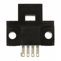
EE-SB5M/SB5MC/SB5V/SB5VC/SB5V-E
Photomicrosensor with 80-mA Switching Capacity that can be Built into Equipment � Built-in amplifier � Models available with 5- to 12-VDC and
5- to 15-VDC input
� CMOS- and TTL-compatible � Model with easy adjustment with an
external sensitivity adjuster (EE-SB5V)
� Special connectors (EE-1001/1006) are
available
� 19-mm sensing distance (EE-SB5V-E) � Convert to PNP output with EE-2002
conversion connector
Ordering Information
Appearance Sensing method Reflective Sensing distance 5 mm Output configuration Light-ON Dark-ON Light-ON Dark-ON 19 mm Light-ON Approx. 2.8 g Weight Approx. 3.0 g Part number EE-SB5M EE-SB5MC EE-SB5V EE-SB5VC EE-SB5V-E
Specifications
� RATINGS
Item Supply voltage Current consumption Maximum forward direct current (IF) Forward voltage (VF) Reverse voltage (VR) Standard reference object Differential distance Reflective EE-SB5M 36 mA max. — — — 0.1 mm
(This table continues on the next page.)
EE-SB5MC
EE-SB5V(-E)
EE-SB5VC
5 to 12 VDC ±10%, ripple (p-p): 10% max.
5 to 15 VDC ±10%, ripple (p-p): 10% max. 48 mA max. (DC current: IF = 25 mA) 30 mA max. 1.5 V max. (IF = 30 mA) 4 V max.
White paper with reflection factor of 90% (standard sensing object: 15 x 15 mm)
�EE-SB5M/SB5MC/SB5V/SB5VC/SB5V-E
EE-SB5M/SB5MC/SB5V/SB5VC/SB5V-E
Specifications Table -- continued from previous page
Item Control output Output configuration Reflective EE-SB5M EE-SB5MC EE-SB5V(-E) EE-SB5VC At 5 to 24 VDC: 80-mA load current (IC) with a residual voltage of 0.8 V max. When driving TTL: 40-mA load current (IC) with a residual voltage of 0.4 V max. Transistor on output stage OFF without detecting object Transistor on output stage ON with detecting object Response frequency* Connecting method Light source Receiver 50 Hz EE-1001/1006 Connectors; soldering terminals GaAs infrared LED with a peak wavelength of 940 nm Si photo-transistor with a sensing wavelength of 850 nm max. ON OFF OFF ON ON OFF
*The response frequency was measured by detecting the following disks rotating.
200 mm dia. Disk
5 mm 15 mm 15 mm 15 mm
� CHARACTERISTICS
Ambient temperature Ambient humidity y Vibration resistance Shock resistance Soldering heat resistance Operating Storage Operating Storage -25°C to 55°C (-13°F to 131°F) -30°C to 80°C (-22°F to 176°F) 45% to 85% 35% to 95% Destruction: 20 to 2,000 Hz (with a peak acceleration of 20G’s), 1.5-mm double amplitude for 4 min each in X, Y, and Z directions Destruction: 500 m/s2 for 3 times each in X, Y, and Z directions 260°±5°C (See Note.) when the portion between the tip of the terminals and the position 1.5 mm from the terminal base is dipped into the solder for 10±1 seconds
Note: This conforms to MIL-STD-750-2031-1.
�EE-SB5M/SB5MC/SB5V/SB5VC/SB5V-E
EE-SB5M/SB5MC/SB5V/SB5VC/SB5V-E
Engineering Data
� OPERATING RANGE (TYPICAL 1)
EE-SB5M(C) Reference object: White paper ( 15 x 15 mm) (reflection factor: 90%)
� OPERATING RANGE (TYPICAL 2)
EE-SB5M(C)
Distance Y (mm)
Distance Y (mm)
Reference object: White paper (15 x 15 mm) (reflection factor: 90%)
Releases
Optical axis X Operates Y
Releases Optical axis X’ Y
Operates
X (mm)
X’ (mm)
� SENSING DISTANCE VS. OBJECT
AREA (TYPICAL)
EE-SB5M(C) Reference object: White paper ( 15 x 15 mm) (reflection factor: 90%)
� SENSING DISTANCE VS. IF EE-SB5V-E
(TYPICAL)
20
Sensing Distance d (mm)
16 12
Distance (mm)
TA = 25°C Reference object White paper: (reflection factor 90%)
8
4
0
5
10
15
20
25
30
Forward Current IF (mA) Area (mm2)
�EE-SB5M/SB5MC/SB5V/SB5VC/SB5V-E
EE-SB5M/SB5MC/SB5V/SB5VC/SB5V-E
Operation
� INTERNAL/EXTERNAL CIRCUIT DIAGRAMS
EE-SB5M(C) Light-ON/Dark-ON
5 to 12 VDC Load (relay) RL Connect RL as shown only when logic circuit is driven. L
EE-SB5V(C), EE-SB5V-E Light-ON/Dark-ON
5 to 15 VDC Load (relay) Main circuit OUT ← IC Logic circuit 0V RL
OUT Main circuit ← IC Logic circuit
LED display 0V L
RF Current-limiting resistor
� TIMING CHART
Light-ON
Incident Interrupted Output transistor Load (relay) Output voltage (logic) ON OFF Operates Releases H L Output transistor Load (relay) Output voltage (logic)
Dark-ON
Incident Interrupted ON OFF Operates Releases H L
Dimensions
Unit: mm (inch)
� EE-SB5M(C), EE-SB5V(C), EE-SB5V-E
25.4 (1.00) 19.0 (0.75) 9.8 (0.39) 6.35 6.95 (0.25) 4.55 (0.18) (0.27) 13.0 (0.51) Optical axis 9.0 (0.35) Two, 3.2 dia. holes
Optical axis
Terminal Arrangement (1) VCC (2) L L (3) OUT OUTPUT (4) GND (0 V)
16.7 (0.66)
13.2 8.0 (0.52) (0.31) 5.5 (0.22) 1.2 (0.05) 6.2 (0.24) 2.55 (0.10) 0.6 (0.02)
1.5
Two, 3.8 dia. holes (1) (2)(3)(4) 0.3 (0.01)
0.8 (0.03)
2.54 (0.10) 1.45 (0.06)
�EE-SB5M/SB5MC/SB5V/SB5VC/SB5V-E
EE-SB5M/SB5MC/SB5V/SB5VC/SB5V-E
� EE-SB5M(C)/SB5V(C)/SB5V-E + EE-1001
22.2 (0.87)
� EE-SB5M(C)/SB5V(C)/SB5V + EE-1006
26 (1.02)
10.8 (0.48) 6.0 (0.24)
16.2 (0.64)
� EE-1001 CONNECTOR
13.0 (0.51) 2.54±0.15 4.0 (0.16) 0.6 (0.02)
� EE-1006 CONNECTOR WITH CABLE
10.8 (0.43) 0.6 (0.02) 16.2 (0.64) 11.8 (0.46) 2.54 (0.10) 5.3 (0.21) (1) (2) (3) (4) 20 (0.79)
6.0 (0.24)
2,000 (78.74)
25 (0.98)
15 (0.59)
2.9±1
Terminal Arrangement (1) Red (Brown) (2) Yellow (Pink) (3) White (Black) (4) Black (Blue)
L OUT
VCC L OUTPUT GND (0 V)
IEC colors are shown in parentheses. Note: Supply 5 to 12 V to the EE-SB5M(C). Wire as shown by the following diagram if the supply voltage exceeds 12 V.
VCC (2) Z GND R VCC (1) VCC (2) = VCC (1) x Z Z+R
Note: Z is the internal impedance between the positive and negative terminals. Model EE-SB5M(C) VCC (2) 5 to 12 V Z (Ω) 360
�EE-SB5M/SB5MC/SB5V/SB5VC/SB5V-E
EE-SB5M/SB5MC/SB5V/SB5VC/SB5V-E
Precautions
Refer to the Technical Information Section for general precautions.
L IF Vcc RF External sensitivity adjuster 0V Output
An external sensitivity adjuster can be connected to the EE-SB5V(C), EE-SB5V-E Photomicrosensor. When connecting the sensitivity adjuster, insert resistor RF (current-limiting resistor), as shown by the diagram. The value of RF is obtainable as follows: RF > (VCC - 1.5 V)/30 mA
OUT
Note: The EE-SB5V(C) and EE-SB5V-E have no constant current circuit to protect the LED. For this reason, the LED will be damaged by excessive current applied to the positive terminal. To prevent potential LED damage, connect a current-limiting resistor, as shown previously.
NOTE: DIMENSIONS SHOWN ARE IN MILLIMETERS. To convert millimeters to inches divide by 25.4.
OMRON ELECTRONICS, INC.
One East Commerce Drive Schaumburg, IL 60173
�
OMRON CANADA, INC.
885 Milner Avenue Scarborough, Ontario M1B 5V8
1-800-55-OMRON
Cat. No. EO5DAX4 1/99 Specifications subject to change without notice.
416-286-6465
Printed in U.S.A.
�
很抱歉,暂时无法提供与“EE-SB5M”相匹配的价格&库存,您可以联系我们找货
免费人工找货