Amp’ed RF, Inc.
(phone) 408 213-9530 (fax) 408 213-9533
Product Specification
Features
Bluetooth Radio Fully embedded Bluetooth v2.0 Serial Profile Class 2 radio Complete RF ready module Wireless data communications Integrated chip antenna 128-bit encryption security Range up to 30m LOS FCC & Bluetooth qualified ST Micro ARM7 microprocessor up to 50MHz Memory 256K bytes flash memory 64K bytes RAM memory Data Rate 2M bps maximum data rate Multipoint capability Serial Interface UART, up to 480K baud (up to 3.25M baud on BT21.2) Buffered SPI interface I2C interface USB v2.0 General I/O 14 general purpose I/O 4x12-bit A/D inputs User Interface AT command set
15mm x 27mm
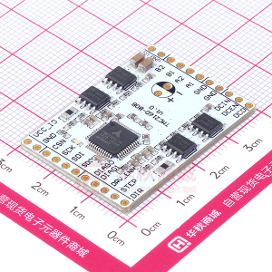
Description
One of the most capable Bluetooth modules available, the BT-21 Bluetooth OEM Module is designed for maximum flexibility. The BT-21 module includes 14 general purpose input/output lines, several serial interface options, analog-to-digital inputs, and up to 2M bps data throughput. The BT-21 is a surface mount PCB module that provides fully embedded, ready to use Bluetooth wireless technology. The reprogrammable flash memory contains embedded firmware for serial cable replacement using the Bluetooth SPP profile. Other popular Bluetooth profiles, such as OBEX, are also available. Customized firmware for peripheral device interaction, power optimization, security, and other proprietary features may be supported and can be ordered pre-loaded and configured.
-
Additional Documentation
BT Hardware Design Guide abSerial User Guide abSerial Reference Guide
©2008 Amp’ed RF Inc 1 9/29/08
1722 Ringwood Ave, Suite 250, San Jose, CA 95131, USA www.ampedrf.com
BT-21 Datasheet Page 1 of 12
�Amp’ed RF, Inc.
(phone) 408 213-9530 (fax) 408 213-9533
Software Architecture
Lower Layer Stack
Full Bluetooth v2.0 data rate (3M bps maximum) Device power modes—active, sleep and deep sleep Wake on Bluetooth feature—optimized power consumption of host CPU Authentication and encryption Encryption key length from 8-bits to 128-bits maximum Persistent FLASH memory—for BD Address and radio parameter storage All ACL (Asynchronous Connection Less) packet types (DM1, DH1, DM3, DH3, DM5, DH5, 2-DH1, 2-DH3, 2-DH5, 3-DH1 3-DH3, 3-DH5, AUX1) SCO (Synchronous Connection Oriented) packet types (HV1, HV2, HV3) Point to multipoint and scatternet support—3 master and 7 slave links allowed (10 active links simultaneously) Park, sniff, and hold modes—fully supported to maximum allowed intervals Master slave switch—supported during connection and post connection Dedicated Inquiry Access Code—for improved inquiry scan performance Dynamic packet selection—channel quality driven data rate to optimize link performance Dynamic power control—interference reduction and link performance Bluetooth test modes—per Bluetooth v2.0 specification 802.11b co-existence—AWMA and AFH Vendor specific HCI commands—to support device configuration and certification test modes
Upper Layer Stack
SPP, OBEX, SDAP, GAP, and DUN protocols RFComm, SDP, and L2CAP supported
HCI Interface
Bluetooth v2.0 specification compliant HCI UART transport layer (H4) Firmware upgrade over UART
APPLICATIONS UPPER LAYER STACK
EVENTS COMMANDS
ARM7 CPU
HCI LM BASEBAND RF HCI STACK
FLASH MEMORY
©2008 Amp’ed RF Inc 2 9/29/08
1722 Ringwood Ave, Suite 250, San Jose, CA 95131, USA www.ampedrf.com
BT-21 Datasheet Page 2 of 12
�Amp’ed RF, Inc.
(phone) 408 213-9530 (fax) 408 213-9533
Hardware Specifications
General Conditions (VIN= 3.0V and 25°C)
Recommended Operating Conditions
Rating Operating Temperature Range Supply Voltage VIN Signal Pin Voltage RF Frequency Min -20 2.8 2400 Typical 3.0 3.0 Max 80 3.4 2483.5 Unit °C Volts Volts MHz
Absolute Maximum Ratings
Rating Storage temperature range Supply voltage, VIN I/O pin voltage, VIO RF input power Min -55 -0.3 -0.3 Typical Max +150 + 3.6 + 4.0 -5 Unit °C Volts Volts dBm
Current Consumption
Modes Typical Power Consumption ACL data 115K Baud UART at max throughput (Master) ACL data 115K Baud UART at max throughput (Slave) Connection, no data traffic, master Connection, no data traffic, slave Connection in sniff (Tsniff=100ms), no data traffic, master Connection in sniff (Tsniff=100ms), no data traffic, slave Connection in sniff (Tsniff=375ms), no data traffic, master Connection in sniff (Tsniff=375ms), no data traffic, slave Standby, without deep sleep Standby, with deep sleep Page/Inquiry scan, deep sleep Avg 35.0 35.0 16.0 24.0 8.0 8.4 2.0 2.5 14.0 0.11 1.4 Unit mA mA mA mA mA mA mA mA mA mA mA
©2008 Amp’ed RF Inc 3 9/29/08
1722 Ringwood Ave, Suite 250, San Jose, CA 95131, USA www.ampedrf.com
BT-21 Datasheet Page 3 of 12
�Amp’ed RF, Inc.
(phone) 408 213-9530 (fax) 408 213-9533
I/O Operating Characteristics
Symbol VIL VIH VOL VOH IOL IOH RPU RPD
Parameter Low-Level Input Voltage High-Level Input Voltage Low-Level Output Voltage High-Level Output Voltage Low -Level Output Current High-Level Output Current Pull-up Resistor Pull-down Resistor
Min 2.1 2.2 80 80
Max 0.9 0.4 4.0 4.0 120 120
Unit Volts Volts Volts Volts mA mA KΩ KΩ
Conditions VIN, 3.0V VIN, 3.0V VIN, 3.0V VIN, 3.0V VOL = 0.4 V VOH = 2.2 V Resistor Turned On Resistor Turned On
Selected RF Characteristics
Parameters Antenna load Radio Receiver Sensitivity level Maximum usable level Input VSWR Radio Transmitter Maximum output power Initial Carrier Frequency Tolerance 20 dB Bandwidth for modulated carrier
Conditions
BT Spec
Typical 50
Unit ohm dBm dBm
BER < .001 with DH5 BER < .001 with DH1
≤ -70 ≥ -20
-84 -9 2.5:1
50 Ω load
-6 to +4 ± 75 ≤ 1000
+5 0 932
dBm kHz kHz
©2008 Amp’ed RF Inc 4 9/29/08
1722 Ringwood Ave, Suite 250, San Jose, CA 95131, USA www.ampedrf.com
BT-21 Datasheet Page 4 of 12
�Amp’ed RF, Inc.
(phone) 408 213-9530 (fax) 408 213-9533
Pin Assignment
Name Type UART Interface RXD TXD CTS RTS Boot 0 GPIO [11] GPIO [12] VDD GND Reset RESETN GPIO [0] GPIO [1] GPIO [2] GPIO [3] GPIO [4] GPIO [5] GPIO [6] GPIO [7] GPIO [8] GPIO [9] GPIO [10] GPIO [13] GPIO [14] GPIO [15] I I/O I/O I/O I/O I/O I/O I/O I/O I/O I/O I/O I/O I/O I/O 3 16 17 19 1 18 20 22 13 4 7 5 15 14 21 Reset input (active low for 5 ms); General Purpose Input/Output General Purpose Input/Output General Purpose Input/Output General Purpose Input/Output General Purpose Input/Output General Purpose Input/Output General Purpose Input/Output General Purpose Input/Output General Purpose Input/Output General Purpose Input/Output General Purpose Input/Output General Purpose Input/Output General Purpose Input/Output General Purpose Input/Output SPI MISO SPI MOSI SPI SS SPI CLK UART 2 RXD UART 2 TXD ADC 0 ADC 1 ADC 2 ADC 3 GPIO – General Purpose Input/Output I O I O I I/O I/O Pin # 8 6 9 10 2 11 12 24 23 Description Receive data Transmit data Clear to send (active low) Request to send (active low) Boot Loader (active high) General Purpose Input/Output General Purpose Input/Output VDD GND ALT Function
Reserved – Available on BT21.2
Power and Ground
© 5 2008 Amp’ed RF Inc 9/29/08
1722 Ringwood Ave, Suite 250, San Jose, CA 95131, USA www.ampedrf.com
BT-21 Datasheet Page 5 of 12
�Amp’ed RF, Inc.
(phone) 408 213-9530 (fax) 408 213-9533
BT-21 Drawing
©2008 Amp’ed RF Inc 6 9/29/08
1722 Ringwood Ave, Suite 250, San Jose, CA 95131, USA www.ampedrf.com
BT-21 Datasheet Page 6 of 12
�Amp’ed RF, Inc.
(phone) 408 213-9530 (fax) 408 213-9533
Hardware Block Diagram
Battery or supply
Regulator
2.75V
2.75V SPI
BP Filter
STLC2500C
RAM ROM
UART
Reset
ARM MCU
GPIO
BT_W akeUp
256K/Flash 64K/RAM
UART
26 MHz Crystal
BT stack up to HCI - abSerial/Application - GAP, SPP, DUN, OBEX - SDP/RFCOMM - L2CAP
BT-21 Bluetooth Module Block Diagram
©2008 Amp’ed RF Inc 7 9/29/08
1722 Ringwood Ave, Suite 250, San Jose, CA 95131, USA www.ampedrf.com
BT-21 Datasheet Page 7 of 12
�Amp’ed RF, Inc.
(phone) 408 213-9530 (fax) 408 213-9533
Hardware Design
Amp’ed RF modules support UART, USB, SPI, and GPIO hardware interfaces. Note that the usage of these interfaces is dependant upon the firmware that is loaded into the module, and is beyond the scope of this document. Notes All unused pins should be left floating; do not ground. All GND pins must be well grounded. The area around the module should be free of any ground planes, power planes, trace routings, or metal for 8 mm from the antenna in all directions. Traces should not be routed underneath the module. Module Reflow Installation The BT-21 is a surface mount Bluetooth module supplied on a 24 pin, 6-layer PCB. The final assembly recommended reflow profiles are: For non Pb-free applications, Sn63Pb37 solder is recommended. Maximum peak temperature of 208° - 210°C (below 220°C). Maximum rise and fall slope after liquidous of < 2°C/second. Maximum rise and fall slope after liquidous of < 2°C/second. Maximum time at liquidous of 50 – 90 seconds. For RoHS/Pb-free applications, Sn96.5/Ag3.0/Cu0.5 solder is recommended. Maximum peak temperature of 230° - 240°C (below 250°C). Maximum rise and fall slope after liquidous of < 2°C/second. Maximum rise and fall slope after liquidous of < 3°C/second. Maximum time at liquidous of 40 – 80 seconds.
© 8 2008 Amp’ed RF Inc 9/29/08
1722 Ringwood Ave, Suite 250, San Jose, CA 95131, USA www.ampedrf.com
BT-21 Datasheet Page 8 of 12
�Amp’ed RF, Inc.
(phone) 408 213-9530 (fax) 408 213-9533
GPIO Interface All GPIOs are capable of sinking and sourcing 4mA of I/O current. GPIO [0] to GPIO [7] are internally pulled down with 100KΩ (nominal) resistors GPIO [8] to GPIO [15] are internally pulled up with 100KΩ (nominal) resistors. UART Interface The UART is compatible with the 16550 industry standard. Four signals are provided with the UART interface. The TXD and RXD pins are used for data while the CTS and RTS pins are used for flow control.
CTS TXD Host RXD RTS
RXD RTS CTS TXD Amp’ed RF Module
Connection to Host Device
©2008 Amp’ed RF Inc 9 9/29/08
1722 Ringwood Ave, Suite 250, San Jose, CA 95131, USA www.ampedrf.com
BT-21 Datasheet Page 9 of 12
�Amp’ed RF, Inc.
(phone) 408 213-9530 (fax) 408 213-9533
Amp’ed RF Module
Typical RS232 Circuit
©0 1 2008 Amp’ed RF Inc 9/29/08
1722 Ringwood Ave, Suite 250, San Jose, CA 95131, USA www.ampedrf.com
BT-21 Datasheet Page 10 of 12
�Amp’ed RF, Inc.
(phone) 408 213-9530 (fax) 408 213-9533
PCB Layout Guidelines
©1 1 2008 Amp’ed RF Inc 9/29/08
1722 Ringwood Ave, Suite 250, San Jose, CA 95131, USA www.ampedrf.com
BT-21 Datasheet Page 11 of 12
�Amp’ed RF, Inc.
(phone) 408 213-9530 (fax) 408 213-9533
FCC Regulatory Compliance
This module has been tested and found to comply with the FCC Part15 Rules. These limits are designed to provide reasonable protection against harmful interference in approved installations. This equipment generates, uses, and can radiate radio frequency energy and, if not installed and used in accordance the instructions, may cause harmful interference to radio communications. However, there is no guarantee that interference will not occur in a particular installation. This device complies with part 15 of the FCC Rules. Operation is subject to the following two conditions: (1) This device may not cause harmful interference, and (2) this device must accept any interference received, including interference that may cause undesired operation. Modifications or changes to this equipment not expressly approved by Amp’ed RF may void the user’s authority to operate this equipment. Modular Approval FCC ID: WDTBTMOD2 In accordance with FCC Part 15, the BT-21 is listed above as a Modular Transmitter device.
FCC Label Instructions
The outside of final products that contain a BT-21 device must display a label referring to the enclosed module. This exterior label can use wording such as the following: “Contains Transmitter Module FCC ID: WDTBTMOD2 or “Contains FCC ID: WDTBTMOD2. Any similar wording that expresses the same meaning may be used.
©2008 Amp’ed RF Inc 12 9/29/08
1722 Ringwood Ave, Suite 250, San Jose, CA 95131, USA www.ampedrf.com
BT-21 Datasheet Page 12 of 12
�