Preliminary
EnerChip™ EH CBC5300
EnerChip™ EH Energy Harvesting Module
Overview
The EnerChip EH CBC5300 is a self-contained Energy Harvesting power module in a 24-pin DIP configuration. The CBC5300 module is designed to accept a wide range of energy transducer inputs, store the harvested power, and deliver managed power to the target system. The purpose of this module is to enable system designers to quickly develop Energy Harvesting applications. A block diagram of the EnerChip EH CBC5300 energy harvesting module is shown in Figure 1.
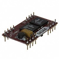
Figure 2: EnerChip EH Module - CBC5300
System Description
Input Power Transducer Input Boost Converter
Input/Output Pins Power Management
The energy harvesting transducer (e.g. photovoltaic cell, piezoelectric material, thermoelectric converter, etc.) converts ambient energy into electrical energy. The output voltage of the energy harvesting transducer is often too low to charge the EnerChip batteries and power the rest of the system directly, so a boost converter is used to boost the energy harvesting transducer voltage to the voltage needed to charge the EnerChip and/or power the system. The charge control block continuously monitors the output of the boost converter. If the output of the boost converter falls below the voltage needed to charge the EnerChips, the charge controller will disconnect the boost converter from the EnerChips. This prevents the EnerChips from back-powering the boost converter in low input power conditions. The power management block is used to protect the EnerChips from discharging too deeply in low input power conditions or abnormally high current load conditions. The power management block also ensures that the load is powered up with a smooth power-on transition. The power management block has a control line (CHARGE) for indication to the system controller that the energy harvester is charging the EnerChips. A control line input (BATOFF) is available for the controller to disconnect itself from the EnerChips when it is necessary to conserve battery life in prolonged low input power conditions. The EnerChip EH CBC5300 as shown in Figure 2 has two CBC050 50µAh EnerChip rechargeable battery cells, for a total 100µAh of capacity.
Page 1 of 11
Charge Control
2 - EnerChip CBC050
Figure 1: EnerChip EH Module Block Diagram
Applications
• Wireless Sensors - Create perpetual sensors with ambient energy and no batteries to change. • Patient Monitoring - Use piezoelectric, thermoelectric, or photovoltaic transducers to power patient status sensors. • Process Control - Sensors and reporting electronics can be powered with motion or fluid flow transducers. • Real Time Location Monitoring - Active RFID and RTLS sensing devices can be powered using energy harvesting. • Environmental Monitoring and Controls Optimize energy using energy harvesting.
DS-72-06 Rev06
©2009 Cymbet Corporation • Tel: +1-763-633-1780 • www.cymbet.com
�Preliminary
CBC5300 Input/Ouput Descriptions and Pin-outs
EnerChip EH CBC5300
The following table describes each of the 24 pins on the module. See the Applications section and Figure 3 for a detailed description of the use of each pin.
Pin Number
1 2 3 4
Label
VIN PGND GATE CHARGE
Description
Transducer power input Same potential as system ground. Tie to GND. Output signal used for setting operating point. Leave unconnected or use as a test point. Active low output from the CBC5300 indicating that the EnerChips have been charged or are being charged. This is an open drain output with an internal 10MΩ pull-up resistor to V0UT. See the section Circuit Recommendations to Save Power for additional information. No pin present No pin present No pin present No pin present Tied to bottom of voltage divider to set VOPER Set peak power operating voltage Tied to top of voltage divider to set VOPER Under voltage lockout select. The nominal set point is 700 mV. Normally, this pin is tied to VIN. To raise the threshold, add one or more series diodes between this pin and VIN. Factory test pin - tie to pins 14, 2 and 24 on target Factory test pin - tie to pins 13, 2 and 24 on target Factory test pin - no connection Input control line to the CBC5300 for disconnecting the EnerChips from the CBC5300 charging circuit. See the section Circuit Recommendations to Save Power for additional information. No pin present No pin present No pin present No pin present Output holding capacitor interface EnerChip power output, connected indirectly to the EnerChips’ positive terminals through an isolation FET. Voltage is one diode drop above the potential at V0UT. System output power (3.6V maximum) System ground
5 6 7 8 9 10 11 12
NPP NPP NPP NPP SIGRTN VOPER VREG UVLO SEL
13 14 15 16
EC2GND EC1GND BATTEST BATOFF
17 18 19 20 21 22
NPP NPP NPP NPP VCAP VBAT
23 24
V0UT GND
DS-72-06 Rev06
©2009 Cymbet Corporation • Tel: +1-763-633-1780 • www.cymbet.com
Page 2 of 11
�Preliminary
VIN PGND GATE CHARGE NPP NPP NPP NPP SIGRTN VOPER VREG UVLO SEL
1 2 3 4 5 6 7 8 9 10 11 12 24 23 22 21 20 19 18 17 16 15 14 13
EnerChip EH CBC5300
GND V0UT VBAT VCAP NPP NPP NPP NPP BATOFF BATTEST EC1GND EC2GND CBC5300 Dimensions Attribute width length height Size 0.7 in [17.18mm] 1.2in [30.48mm] 0.9in [5.00mm]
24-Pin DIP Module Connecting the CBC5300 to the System
The CBC5300 board has two control lines that can be connected to a microcontroller (MCU) for the purpose of conserving available energy, using incoming power efficiently, and extending EnerChip battery life. The table below describes the functionality of the connector pins. • VOUT is the DC output voltage from the CBC5300 and is approximately 3.5V depending on load current. It provides power to the system according to the Operating Characteristics table shown below. • VBAT is normally used for factory test purposes. It is indirectly connected to the on-board EnerChips through an isolation pass transistor. The voltage on VBAT is connected to VOUT by a diode and thus the voltage at VOUT is one diode drop lower than the voltage on VBAT. It is recommended that VBAT remain disconnectted from external circuits. In no event should VBAT be used for any purpose other than to provide power to a load. • BATOFF is typically controlled by a microcontroller I/O line. When driven high, the on-board EnerChips will be disconnected from the charging source of the CBC5300. This feature allows all available power to be delivered to the load rather than to charging the EnerChips, a useful mode when limited transducer power is available or when higher operating current is required from the system. When BATOFF is driven low, the interaction between the charging source and the CBC5300 behaves normally. In other words, when BATOFF is low the EnerChips will always be charging when sufficient input power is available. • CHARGE is an output signal from the CBC5300 that will be forced low under one of two conditions: » When transducer output power is very low, a low level on CHARGE indicates that the EnerChips have been charged. » CHARGE will also be driven low when transducer output power is more than sufficient to operate the boost converter and charge the EnerChips at peak rate, regardless of the state of charge of the EnerChips. Programming an MCU timer to allow enough charging time to elapse after the assertion of CHARGE will ensure that the EnerChips are fully charged before using them to deliver power to the system. The advantage is that the system is then aware of the minimum reservoir of energy available in the event transducer power goes to zero.
DS-72-06 Rev06
©2009 Cymbet Corporation • Tel: +1-763-633-1780 • www.cymbet.com
Page 3 of 11
�Preliminary
EnerChip EH CBC5300
Figure 3: CBC5300 Application Circuit Schematic
Operating Characteristics
Parameter
Parasitic Load Current
Condition
Boost converter off Boost converter on Battery charged Operating 25°C 4.7kΩ load 25°C
Min
3.5 0.25 3.0 600 0 5000 1000 2500 500 -
Typical
800 20 3.55 4.06 3.3 0.7 2.5 25 10 50 100
Max
3.6 4 3.6 70 -
Units
nA µA V V V V V µA % per year °C minutes minutes µAh
VOUT , 2µA Load VIN VBAT Charging Voltage
Battery Cutoff Voltage UVLO Trip Select Voltage Pulse Discharge Current Operating Temperature Recharge Cycles (to 80% of rated capacity; 4.1V charge voltage) 25°C 40°C
(1)
20 ms 25°C 10% depth-of-discharge 50% depth-of discharge 10% depth-of-discharge 50% depth-of-discharge From 50% state-of-charge From deep discharge 16 µA discharge; 25°C
Self-Discharge (non-recoverable average)
Recharge Time (to 80% of rated capacity) Capacity
(1) For design guidelines in selecting an external boost capacitor, see the section titled Designing for Pulse Discharge Currents in Wireless Devices.
Application Overview
The following sections provide design guidance and system level considerations for optimizing the performance and service life of the CBC5300.
Specifications subject to change without notice.
DS-72-06 Rev06
©2009 Cymbet Corporation • Tel: +1-763-633-1780 • www.cymbet.com
Page 4 of 11
�Preliminary
EnerChip EH CBC5300
Designing for Pulse Discharge Currents in Wireless Devices
Pulse discharge currents place special demands on batteries. Repeated delivery of pulse currents exceeding the recommended load current of a given chemistry will diminish the useful life of the cell. The effects can be severe, depending on the amplitude of the current and the particular cell chemistry and construction. Pulse currents of tens of milliamperes are common in wireless sensor systems during transmit and receive modes. Moreover, the internal impedance of the cell often results in an internal voltage drop that precludes the cell from delivering the pulse current at the voltage necessary to operate the external circuit. One method of mitigating such effects is to place a low Equivalent Series Resistance (ESR) capacitor across the battery. The battery charges the capacitor between discharge pulses and the capacitor delivers the pulse current to the load. Specifying the capacitance for a given battery in an application is a straightforward procedure, once a few key parameters are known. The key parameters are: • • • • • • Battery impedance (at temperature and state-of-charge) Battery voltage (as a function of state-of-charge) Operating temperature Pulse current amplitude Pulse current duration Allowable voltage droop during pulse discharge
Two equations will be used to calculate two unknown parameters: 1) the output capacitance needed to deliver the specified pulse current of a known duration; 2) the latency time that must be imposed between pulses to allow the capacitor to be recharged by the battery. Both formulae will assume that the capacitor ESR is sufficiently low to result in negligible internal voltage drop while delivering the specified pulse current; consequently, only the battery resistance will be considered in the formula used to compute capacitor charging time and only the load resistance will be considered when computing the capacitance needed to deliver the discharge current. The first step in creating a battery-capacitor couple for pulse current applications is to size the capacitance using the following formula: Discharge formula: C = t / R * [-ln (Vmin / Vmax)] where: C = output capacitance, in parallel with battery; t = pulse duration; R = load resistance = Vout(average) / Ipulse Vmin and Vmax are determined by the combination of the battery voltage at a given state-of-charge and the operating voltage requirement of the external circuit. Once the capacitance has been determined, the capacitor charging time can be calculated using the following formula: Charge formula: t = R * C * [- ln (1 - Vmin / Vmax)] where: t = capacitor charging time, from Vmin to Vmax R = battery resistance C = output capacitance, in parallel with battery
DS-72-06 Rev06
©2009 Cymbet Corporation • Tel: +1-763-633-1780 • www.cymbet.com
Page 5 of 11
�Preliminary
EnerChip EH CBC5300
Again, Vmin and Vmax are functions of the battery voltage and the circuit operating specifications. Battery resistance varies according to temperature and state-of-charge as described above. Worst-case conditions are often applied to the calculations to ensure proper system operation over temperature extremes, battery condition, capacitance tolerance, etc. The composite resistance of the 2-cell parallel EnerChip arrangement on the CBC5300 board ranges from 750Ω to about 1500Ω. At the output stage, a 1000µF, low resistance capacitor in parallel with the EnerChips delivers peak power to the external circuit, which might contain a microcontroller and radio, for example. The EnerChips deliver the lower level, continuous (average) power to the load. EnerChip electrical resistance is fairly constant from 100% state-of-charge to about 10% state-of-charge; its internal resistance begins to increase significantly only when the state-of-charge is reduced below approximately 10%. A question often arises: “How many radio transmission pulses can be delivered by the two EnerChips on the CBC5300?” The answer depends on a number of factors including the pulse current amplitude, pulse duration, operating temperature, etc. The question will be addressed by way of example. To extend the life of the EnerChips, assume the EnerChips will be cutoff from the load when a 50% stateof-charge has been reached. (See the section titled Battery Protection for a description of how this is accomplished.) With 100µAh of combined capacity in the two EnerChips, a 50% state-of-charge is simply 50µAh. Further, supppose each radio transmission uses 30mA for 20ms. The charge per pulse is: 30mA * 20ms = 600µA-seconds = 0.167µAh. That amount of charge is transferred from the EnerChips into the output capacitor, which then delivers the charge to the load at the rate demanded by the radio. On the CBC5300, there is a series diode between the output capacitor and the output pin (VOUT2), resulting in a diode voltage drop that must be taken into account. In that scenario, 50% of the 100µAh allows 50µAh / 0.167µAh = 300 transmissions to be made if no ambient power is available (i.e., when CHARGE is high). In this example, the background (sleep) current that is drawn between transmissions has been neglected. Use actual power consumption numbers to arrive at the number of transmissions available in any given application. The MCU can be programmed to utilize this information to conserve power and maximize the service life of the EnerChips, as described in the following sections.
Battery Protection
The CBC5300 energy harvester module contains a low battery cutoff circuit that prevents the EnerChips from being completely discharged - a condition that would permanently damage the battery. The cutoff circuit places a parasitic 800nA load on the battery - a load that would discharge the two EnerChips in approximately 125 hours, or just over 5 days. If the EnerChips are allowed to reach the cutoff voltage at such low discharge currents, their specified cycle life will be reached after a few hundred of such deep discharge cycles. To avoid this condition and extend the service life of the EnerChip, it is advisable to program the MCU to count transmission cycles or elapsed time to determine when the EnerChips’ state-of-charge is approximately 50%, at which time the MCU would force itself or another system circuit element to briefly draw high power from the CBC5300, forcing the CBC5300 circuit into a cutoff mode and thereby disconnecting the EnerChips from the circuit. Drawing a brief burst of a few milli-Amperes from the CBC5300 will force the cutoff condition to occur within a few seconds. This will ensure that the charge/discharge cycle life of the EnerChips will be greater than 5000, as rated. To calculate the number of hours the EnerChips are capable of supplying energy to the load, add the cutoff current to the average load current drawn by the system and divide the sum into the combined 100µAh capacity of the two EnerChips. The quotient is the number of hours until the EnerChip is totally depleted. Divide that number in half to reach the 50% depth-of-discharge time.
Guidelines for Attaching Energy Harvesting Transducers
Energy harvesting transducers (e.g., inductive, piezoelectric, thermoelectric) may be attached to the CBC5300. ©2009 Cymbet Corporation • Tel: +1-763-633-1780 • www.cymbet.com
DS-72-06 Rev06
Page 6 of 11
�Preliminary
EnerChip EH CBC5300
As configured, the CBC5300 will operate with many transducer types. However, performance specifications of transducers - namely output impedance - will affect the power conversion efficiency of the CBC5300 kit as designed. Please contact Cymbet Applications Engineering at the phone number shown below to discuss your specific application and desired transducer(s). The CBC5300 module is designed to work with transducers having an output impedance over the range of 58Ω to 4kΩ and an input voltage range of 270mV to 1.5V. The minimum open circuit voltage to start operation is 700mV. Peak efficiency will occur at a nominal transducer input voltage of 800mV to 1.0V at 1kΩ. Operating characteristics for most transducer types are typically available from the manufacturer’s data sheet. An example photovoltaic cell operating curve is shown below. Output impedance, operating voltage, and peak power point can also be verified by empirical measurements. To do this, measure the load voltage and current as a variable load impedance across the transducer is swept over a broad enough range where the peak power point can be found by finding the maximum product of the measured load voltage and current.
VOC: Open-circuit voltage ISC: Short-circuit current VOP: Optimum operating voltage IOP: Optimum operating current PMAX: Maximum operating power Current-Voltage Curve
To configure the CBC5300 to work with a given transducer, the optimal transducer operating voltage point must first be obtained though the manufacturer’s data sheet or from empirical measurements. Next calculate the values needed for a voltage divider to set the operating voltage point on the VOPER pin (pin 10). The top of the voltage divider shown in Figure 3 uses VREG (pin 11) as its voltage source; the bottom of the voltage divider is connected to ground. VOPER is equal to VREG * (R2 / (R1 + R2)), where VREG is nominally 4.06V and R2 (bottom resistor) is in the range of 500kΩ to 1MΩ with the optimal value around 750kΩ. Note: Better circuit performance (i.e., less input ripple voltage) will be obtained if R2 is made smaller than 750kΩ. A more useful formula is: R1 = R2 * ((VREG / VOPER) - 1). Example: For a 1kΩ photovoltaic cell with operating voltage of 1.01V, R1 can be determined as R1 = 1MΩ * ((4.06V / 1.01V) - 1) = 3.02MΩ. A 3.01MΩ resistor is the nearest standard value. R2 was chosen as a standard resistor value. 750kΩ for R2 is also a standard resistor value but the VOPER voltage will be further away from nominal due to the standard resistor values available for R1. Capacitor C1 (47µF) is used to set the bandwidth of the boost converter control loop. If a low impedance transducer is used the value of C1 might have to be reduced in value. This can be verified using an oscilloscope to check the waveform on GATE (pin 3). The waveform should be three pulses followed by a longer interval, followed again by three pulses. The three pulses will have approximately 16.7µs of high duration followed by 16.7µs of low duration. If more than three pulses are in the waveform then the value of C1 should be reduced to obtain the nominal waveform.
Setting the Under Voltage Lockout Voltage
The under voltage lockout (UVLO SEL) voltage should be set at or above the operating point, VOPER, in order to prevent the EnerChip from inadvertently powering the boost converter when insufficient input transducer power is available. Normally, UVLO should be set to a value that is 20% to 80% above VOPER. UVLO SEL can be set by adding one or more series diodes between UVLO SEL and VIN. For example, the nominal voltage at UVLO SEL is 700mV; to raise it to 1.4V, insert one standard silicon diode. To reach intermediate voltages, Schottky diodes may be used.
DS-72-06 Rev06
©2009 Cymbet Corporation • Tel: +1-763-633-1780 • www.cymbet.com
Page 7 of 11
�Preliminary
EnerChip EH CBC5300
System Level Considerations when Using a Low Power Energy Harvester
The CBC5300 is capable of supplying 10s to 100s of µW of continuous power to the load. Most applications operating with radios and microcontrollers typically need 10s to 100s of mW of power under peak load conditions. The disparity between what is available and what is needed can be made up by limiting the amount of time the load is powered and waiting sufficient time for the energy harvester to replenish the energy storage device before the subsequent operation commences. In typical remote RF sensor applications, the ‘on’ time will be on the order of 5-20ms, with an ‘off’ time of several seconds to several hours depending on the application and available energy source. The duty cycle is an important consideration when designing a wireless system. While it is relatively straightforward to calculate a power budget and design a system to work within the constraints of the power and energy available, it is easy to overlook the power required to initialize the system to a known state and to complete the radio link with the host system or peer nodes in a mesh network. The initialization phase can sometimes take two to three times the power needed for steady state operation. Ideally, the hardware should be in a low power state when the system power-on reset is in its active state. If this is not possible, the microcontroller should place the hardware in a low power state as soon as possible. After this is done, the microcontroller should be put into a sleep state long enough for the energy harvester to replenish the energy storage device. If the power budget is not exceeded during this phase, the system can continue with its initialization. Next, the main initialization of the system, radio links, analog circuits, and so forth, can begin. Care should be taken to ensure that the time the system is on during this phase does not exceed the power budget. Several sleep cycles might be needed to ‘stairstep’ the system up to its main operational state. The Cymbet CBC5300 energy harvester module has a handshake line CHARGE to indicate to the microcontroller when energy is available. Another way to know whether energy is available is to have the microcontroller monitor the voltage on its power bus using one its internal A/D converters.
Circuit Recommendations to Save Power
In most system power budgets, the peak power required is not as critical as the length of time the power is required. Careful selection of the message protocol for the RF link can have a significant impact on the overall power budget. In many cases, using higher power analog circuits that can be turned on, settle quickly, and be turned off can decrease the overall energy consumed. Microcontroller clock frequency can also have a significant impact on the power budget. In some applications it might be advantageous to use a higher microcontroller clock frequency to reduce the time the microcontroller and peripheral circuits are active. Avoid using circuits that bias microcontroller digital inputs to mid-level voltages; this can cause significant amounts of parasitic currents to flow. Use 10MΩ to 22MΩ pull-up/down resistors where possible. However, be aware that high circuit impedances coupled with parasitic capacitance can make for a slow rise/fall time that can place the voltage on the microcontroller inputs at mid-levels, resulting in parasitic current flow. One solution to the problem is to enable the internal pull-up/down resistor of the microcontroller input to force the input to a known state, then disable the resistor when it’s time to check the state of the line. If using the microcontroller’s internal pull-up/down resistors on the inputs to bias push-button switches in a polled system, leave the pull-up/ down resistor disabled and enable the resistor only while checking the state of the input port. Alternatively, in an interrupt-driven system, disable the pull-up/down resistor within the first few instructions in the interrupt service routine. Enable the pull-up/down resistor only after checking that the switch has been opened. Microcontroller pull-up/down resistors are typically less than 100kΩ and will present a relatively large load on the system if left on continuously while a switch is being pressed, for example, or if held for any significant length of time. For even greater reduction in power, use external pull-up/down resistors in the 10MΩ to 22MΩ range. Bias the external resistor not with the power rail but with a microcontroller port. The same algorithm used for internal pull-up/down resistors can then be used to save power. The CHARGE line on the CBC5300 has a 10MΩ pull-up resistor with a very slow rise time. Use an internal microcontroller pull-down resistor to force the CHARGE line low all of the time and then disable the pull-down resistor to check the state of the line. This will keep the CHARGE line from biasing the input at mid level for long periods of time which could case large parasitic currents to flow. ©2009 Cymbet Corporation • Tel: +1-763-633-1780 • www.cymbet.com
DS-72-06 Rev06
Page 8 of 11
�Preliminary
EnerChip EH CBC5300
The CBC5300 energy harvester module has a feature for disabling the on-board EnerChip thin film batteries. A handshake line BATOFF is provided for use of this feature. A high level will disable the EnerChips. This is useful in very low ambient energy conditions to steer all of the available energy into the load. EnerChip batteries have very low self-discharge rates (typically 2.5% per year) so it is not necessary to continuously charge them.
Troubleshooting Test Procedure
1) Using a voltmeter, put the ground lead on pin 24 and probe VIN (pin 1). Voltage should be equal to VOPER. This test verifies operation of the input power transducer. 2) Probe right side of the tantalum capacitor (brown bar side) on the CBC5300 module. Voltage should be between 4.5V and 9V depending on ambient light and battery state-of-charge. This test verifies operation of the boost converter. 3) Probe VCAP (pin 21). Voltage should be 4.06V, or steadily increasing if there is no output voltage. When the capacitor voltage reaches 3.8V, VBAT will switch from zero volts to the voltage across VCAP. VOUT will switch from zero volts to the voltage across VCAP, less one diode drop. Note the capacitor attached to VCAP will not be charging if the EnerChips are depleted. When the CBC5300 is first powered up, the CBC5300 will first charge the EnerChips, then charge the output capacitor connected to VCAP, then switch on the output when that capacitor is charged. 4) Probe VBAT (pin 22). This pin should be at 4.06V. 5) Probe VOUT (pin 23). This pin should be at 3.5V. 6) Probe CHARGE (pin 4). This pin should be at zero volts if the EnerChips are charged and enough ambient energy is available to operate the CBC5300 module. Depending on the input impedance of the voltmeter, a high level on this pin would read between 1.0V and 3.5V. If none of the above works, check pin 1 on one of the EnerChips on the CBC5300 module (with it plugged into the target application board), as indicated in the figure below. It should read approximately 3.9V. If the voltage is less than 3.0V, the EnerChips have been damaged. In applications where a radio is being used - as in wireless sensor netorks - there can sometimes be external electrical interference with the radio signal that causes the radio receiver to stay on longer than normal. If this happens, the CBC5300 output capacitor will become discharged and the low battery cutoff circuit will engage, isolating the EnerChips from the load. If this happens it can take from several minutes to an hour or more for the EnerChips and output capacitor to be recharged.
EnerChip Pin 1
DS-72-06 Rev06
©2009 Cymbet Corporation • Tel: +1-763-633-1780 • www.cymbet.com
Page 9 of 11
�Preliminary
Frequently Asked Questions
Q: A:
EnerChip EH CBC5300
I am not sure if I have enough input power to charge the battery? Probe right side of the tantalum capacitor (brown bar side) on the CBC5300 module. Voltage should be between 4.5V and 9V depending on input power and battery state-of-charge. This test verifies operation of the boost converter. What if I short-circuit the output? The disconnect circuit will disconnect the battery from the output after the capacitor is discharged below about 3.0V. This prevents the battery from being discharged too deeply. The battery will automatically reconnect after the capacitor is recharged. What happens if I want to run a larger pulse current application? See application note AN-1025. The output capacitor can be sized to drive almost any load as long as the duration is not too long. AN-1025 describes how to calculate the capacitor size. Are the batteries on the board safe and ‘green’? Yes; there are no safety issues with the Cymbet EnerChip. All of the components are ‘green.’ What happens if the cell is short-circuited? Will it explode or leak harmful chemicals? No. There are no harmful chemicals to leak and the battery will not explode. The VBAT line and the VOUT2 line are at different potentials. Why? The VBAT line is the raw battery output. The VOUT2 line is down-regulated to provide a lower voltage for 3.3V +/- 10% applications. How long will the CBC5300 module operate with no ambient light? This depends on many factors, including power consumption, EnerChip state-of-charge, operating temperature, etc. The on-board EnerChips provide 100µAh of discharge capacity when fully charged. How long will the CBC5300 module last if I use it every day and input power is available most of the time? The CBC5300 module should last at least 10 years. How long will the two cells on the CBC5300 module hold a charge, assuming no input power? The self-discharge of the cell is a function of several parameters, including temperature. For the selfdischarge specifications, see the product data sheets at http://www.cymbet.com/content/products. asp . What happens if the cell is left in a discharged state for a long period of time? Leaving the cell in a discharged state is not detrimental to the cell performance. I see no voltage on VBAT or VOUT2. Make sure there is sufficient input power to operate the boost converter and that the output is not short-circuited.
Q: A:
Q: A: Q: A: Q: A: Q: A: Q: A: Q: A: Q: A:
Q: A: Q: A:
DS-72-06 Rev06
©2009 Cymbet Corporation • Tel: +1-763-633-1780 • www.cymbet.com
Page 10 of 11
�Preliminary
EnerChip EH CBC5300
Ordering Information
EnerChip Part Number
CBC5300-24C
Description
EnerChip EH CBC5300 module
Notes
shipped in tubes
Associated Products and Evaluation Kits
EVALUATION KIT
ANT Energy Harvesting Eval Kit General Purpose Energy Harvesting Eval Kit Texas Intruments Wireless Sensor Energy Harvesting Demo Kit
Description
Energy Harvesting Kit for ANT Dnynastream ANTDKT3 Demo Kit Energy Harvesting Kit for various tranducers and system prototyping Solar Energy Harvesting Demo Kit for the Texas Intruments MSP430/ ChipCon2500
Catalog Number
CBC-EVAL-07 CBC-EVAL-08 eZ430-RF2500-EH
Disclaimer of Warranties; As Is The information provided in this data sheet is provided “As Is” and Cymbet Corporation disclaims all representations or warranties of any kind, express or implied, relating to this data sheet and the Cymbet battery product described herein, including without limitation, the implied warranties of merchantability, fitness for a particular purpose, non-infringement, title, or any warranties arising out of course of dealing, course of performance, or usage of trade. Cymbet battery products are not approved for use in life critical applications. Users shall confirm suitability of the Cymbet battery product in any products or applications in which the Cymbet battery product is adopted for use and are solely responsible for all legal, regulatory, and safety-related requirements concerning their products and applications and any use of the Cymbet battery product described herein in any such product or applications.
Cymbet, the Cymbet logo, and EnerChip are Cymbet Corporation Trademarks ©2009 Cymbet Corporation • Tel: +1-763-633-1780 • www.cymbet.com
DS-72-06 Rev06
Page 11 of 11
�