D a t a S h e e t , R e v. 1 . 0 , M ar c h 2 00 8
B TS 43 00 S G A
Smart High-Side Power Switch
A u to m o t i v e P o w e r
�BTS 4300SGA
1
Overview 3
2
Block Diagram 5
3
3.1
3.2
3.3
Pin Configuration 6
Pin Assignment 6
Pin Definitions and Functions 6
Voltage and Current Definition 7
4
4.1
4.2
4.3
General Product Characteristics 8
Absolute Maximum Ratings 8
Functional Range 9
Thermal Resistance 9
5
5.1
5.2
5.3
5.4
Power Stage 10
Output ON-State Resistance 10
Turn ON / OFF Characteristics 10
Inductive Output Clamp 11
Electrical Characteristics Power Stage 12
6
6.1
6.2
6.3
6.4
6.5
Protection Mechanisms 13
Undervoltage Protection 13
Overvoltage Protection 13
Reverse Polarity Protection 14
Overload Protection 14
Electrical Characteristics Protection Functions 16
7
7.1
7.2
7.2.1
7.2.2
7.3
Diagnostic Mechanism 17
ST Pin 17
ST Signal in Case of Failures 17
Diagnostic in Open Load, Channel OFF 17
ST Signal in case of Over Temperature 19
Electrical Characteristics Diagnostic Functions 20
8
8.1
8.2
Input Pin 21
Input Circuitry 21
Electrical Characteristics 21
9
9.1
Application Information 22
Further Application Information 22
10
Package Outlines 23
11
Revision History 24
Datasheet
2
1.0, 2007-19-12
�Smart High-Side Power Switch
1
BTS4300SGA
Overview
Basic Features
•
•
•
•
•
•
•
•
•
•
Fit for 12V application
One Channel device
Very Low Stand-by Current
CMOS Compatible Inputs
Electrostatic Discharge Protection (ESD)
Optimized Electromagnetic Compatibility
Logic ground independent from load ground
Very low leakage current from OUT to the load in OFF state
Green Product (RoHS compliant)
AEC Qualified
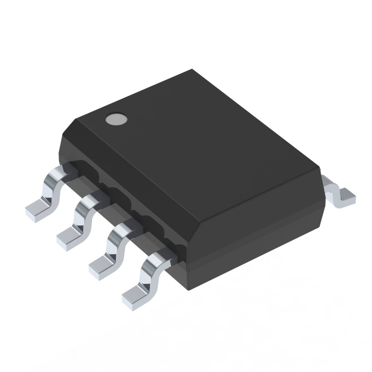
PG-DSO-8-24
Description
The BTS4300SGA is a single channel Smart High-Side Power Switch. It is embedded in a PG-DSO-8-24 package,
providing protective functions and diagnostics. The power transistor is built by a N-channel power MOSFET with
charge pump. The device is monolithically integrated in Smart technology. It is specially designed to drive Relay
or LED in the harsh automotive environment.
Table 1
Electrical Parameters (short form)
Parameter
Symbol
Value
Operating voltage range
VSOP
VS (AZ)
RDS(ON)
IL (nom)
IL_SCR
IS(off)
-Vs(REV)
5V .... 34V
Over voltage protection
Maximum ON State resistance at Tj = 150°C
Nominal load current
Minimum current limitation
Standby current for the whole device with load
Maximum reverse battery voltage
41V
600mΩ
0.4A
0.4A
26µA
32V
Diagnostic Feature
•
•
Open drain diagnostic output
Open load detection in OFF state
Type
Package
Marking
BTS4300SGA
PG-DSO-8-24
4300SGA
Data Sheet
3
Rev. 1.0, 2008-03-18
�BTS4300SGA
Overview
Protection Functions
•
•
•
•
•
•
•
Short circuit protection
Overload protection
Current limitation
Thermal shutdown with restart
Overvoltage protection (including load dump)
Loss of ground and loss of battery protection
Electrostatic discharge protection (ESD)
Application
•
All types of relays, resistive and capacitive loads
Data Sheet
4
Rev. 1.0, 2008-03-18
�BTS4300SGA
Block Diagram
2
Block Diagram
VS
voltage sensor
internal
power
supply
over
temperature
driver
logic
IN
gate control
&
charge pump
ESD
protection
T
clamp for
inductive load
over current
switch off
OUT
open load detection
ST
GND
Figure 1
Data Sheet
Block diagram.emf
Block diagram for the BTS4300SGA
5
Rev. 1.0, 2008-03-18
�BTS4300SGA
Pin Configuration
3
Pin Configuration
3.1
Pin Assignment
GND
1
8
VS
IN
2
7
VS
OUT
3
6
VS
ST
4
5
VS
Figure 2
Pin Configuration
3.2
Pin Definitions and Functions
Pin
Symbol
Function
1
GND
Ground; Ground connection
2
IN
Input channel; Input signal. Activate the channel in case of logic high level
3
OUT
Output; Protected High side power output channel
4
ST
Diagnostic feedback; of channel. Open drain.
5, 6, 7, 8
VS
Battery voltage; Design the wiring for the simultaneous max. short circuit current
and also for low thermal resistance
Data Sheet
6
Rev. 1.0, 2008-03-18
�BTS4300SGA
Pin Configuration
3.3
Voltage and Current Definition
Figure 3 shows all terms used in this data sheet, with associated convention for positive values.
IS
VS
VD S
VS
IIN
IN
IL
OUT
VIN
VOU T
IST
ST
V ST
GND
R GND
IGN D
Voltage and current convention
single avec diag.vsd
Figure 3
Data Sheet
Voltage and current definition
7
Rev. 1.0, 2008-03-18
�BTS4300SGA
General Product Characteristics
4
General Product Characteristics
4.1
Absolute Maximum Ratings
Absolute Maximum Ratings 1)
Tj = 25 °C; (unless otherwise specified)
Pos.
Parameter
Symbol
Limit Values
Unit
Conditions
–
Min.
Max.
–
40
V
0
32
V
0
28
V
Voltages
4.1.1
4.1.2
4.1.3
VS
Reverse polarity Voltage
- VS(REV)
Supply voltage for short circuit protection Vbat(SC)
Supply voltage
RECU = 20mΩ,
RCable=16mΩ/m,
LCable=1µH/m,
l = 0 or 5m 2)
see Chapter 6
Input pins
4.1.4
Voltage at INPUT pins
4.1.5
Current through INPUT pins
VIN
IIN
-10
16
V
–
-5
5
mA
–
Power stage
4.1.6
Load current
| IL |
–
IL(LIM)
A
–
4.1.7
Power dissipation (DC),
PTOT
–
0.8
W
4.1.8
Inductive load switch off energy
dissipation, Single pulse
EAS
–
800
mJ
TA=85°C,
Tj
很抱歉,暂时无法提供与“BTS4300SGAXUMA1”相匹配的价格&库存,您可以联系我们找货
免费人工找货