H i g h c u r r e n t P R O F E T TM
BTS50060-1TEA
Smart High-Side Power Switch
One Channel
Datasheet
Rev. 1.2, 2011-09-01
Automotive
�BTS50060-1TEA
1
Overview . . . . . . . . . . . . . . . . . . . . . . . . . . . . . . . . . . . . . . . . . . . . . . . . . . . . . . . . . . . . . . . . . . . . . . . 3
2
Block Diagram . . . . . . . . . . . . . . . . . . . . . . . . . . . . . . . . . . . . . . . . . . . . . . . . . . . . . . . . . . . . . . . . . . . 4
3
3.1
3.2
3.3
Pin Configuration . . . . . . . . . . . . . . . . . . . . . . . . . . . . . . . . . . . . . . . . . . . . . . . . . . . . . . . . . . . . . . . .
Pin Assignment . . . . . . . . . . . . . . . . . . . . . . . . . . . . . . . . . . . . . . . . . . . . . . . . . . . . . . . . . . . . . . . . . . .
Pin Definitions and Functions . . . . . . . . . . . . . . . . . . . . . . . . . . . . . . . . . . . . . . . . . . . . . . . . . . . . . . . .
Definition of Terms . . . . . . . . . . . . . . . . . . . . . . . . . . . . . . . . . . . . . . . . . . . . . . . . . . . . . . . . . . . . . . . .
4
4.1
4.2
4.3
General Product Characteristics . . . . . . . . . . . . . . . . . . . . . . . . . . . . . . . . . . . . . . . . . . . . . . . . . . . . 6
Absolute Maximum Ratings . . . . . . . . . . . . . . . . . . . . . . . . . . . . . . . . . . . . . . . . . . . . . . . . . . . . . . . . . 6
Functional Range . . . . . . . . . . . . . . . . . . . . . . . . . . . . . . . . . . . . . . . . . . . . . . . . . . . . . . . . . . . . . . . . . 9
Thermal Resistance . . . . . . . . . . . . . . . . . . . . . . . . . . . . . . . . . . . . . . . . . . . . . . . . . . . . . . . . . . . . . . 10
5
5.1
5.1.1
5.1.2
5.1.3
5.1.4
5.2
5.3
5.3.1
5.3.2
5.3.3
5.3.4
5.3.5
5.3.6
5.3.7
5.4
5.4.1
5.4.2
5.4.3
5.5
Functional Description . . . . . . . . . . . . . . . . . . . . . . . . . . . . . . . . . . . . . . . . . . . . . . . . . . . . . . . . . . .
Power Stage . . . . . . . . . . . . . . . . . . . . . . . . . . . . . . . . . . . . . . . . . . . . . . . . . . . . . . . . . . . . . . . . . . . .
Switching a Resisitve Load . . . . . . . . . . . . . . . . . . . . . . . . . . . . . . . . . . . . . . . . . . . . . . . . . . . . . . .
Switching an Inductive Load - Infineon® SMART CLAMPING . . . . . . . . . . . . . . . . . . . . . . . . . . . .
Switching a Capacitive Load . . . . . . . . . . . . . . . . . . . . . . . . . . . . . . . . . . . . . . . . . . . . . . . . . . . . . .
Inverse Load Current Operation . . . . . . . . . . . . . . . . . . . . . . . . . . . . . . . . . . . . . . . . . . . . . . . . . . .
Input Circuit . . . . . . . . . . . . . . . . . . . . . . . . . . . . . . . . . . . . . . . . . . . . . . . . . . . . . . . . . . . . . . . . . . . . .
Protection Functions . . . . . . . . . . . . . . . . . . . . . . . . . . . . . . . . . . . . . . . . . . . . . . . . . . . . . . . . . . . . . .
Protection by Over Current Shutdown . . . . . . . . . . . . . . . . . . . . . . . . . . . . . . . . . . . . . . . . . . . . . . .
Protection by Over Temperature Shutdown . . . . . . . . . . . . . . . . . . . . . . . . . . . . . . . . . . . . . . . . . .
Infineon® INTELLIGENT LATCH . . . . . . . . . . . . . . . . . . . . . . . . . . . . . . . . . . . . . . . . . . . . . . . . . .
Reverse Polarity Protection . . . . . . . . . . . . . . . . . . . . . . . . . . . . . . . . . . . . . . . . . . . . . . . . . . . . . . .
Protection during Loss of Ground . . . . . . . . . . . . . . . . . . . . . . . . . . . . . . . . . . . . . . . . . . . . . . . . . .
Protection during Loss of Load or Loss of VS Condition . . . . . . . . . . . . . . . . . . . . . . . . . . . . . . . . .
Protection during ESD or Over Voltage Condition . . . . . . . . . . . . . . . . . . . . . . . . . . . . . . . . . . . . . .
Diagnosis Functions . . . . . . . . . . . . . . . . . . . . . . . . . . . . . . . . . . . . . . . . . . . . . . . . . . . . . . . . . . . . . .
Sense Output . . . . . . . . . . . . . . . . . . . . . . . . . . . . . . . . . . . . . . . . . . . . . . . . . . . . . . . . . . . . . . . . . .
Enhancing Accuracy of the Sense Output by End of Line Calibration . . . . . . . . . . . . . . . . . . . . . . .
Short-to-Battery detection / Open Load Detection in OFF state . . . . . . . . . . . . . . . . . . . . . . . . . . .
Undervoltage Shutdown & Restart . . . . . . . . . . . . . . . . . . . . . . . . . . . . . . . . . . . . . . . . . . . . . . . . . . .
12
12
12
12
13
13
14
15
15
16
16
16
17
17
18
19
19
21
21
22
6
6.1
6.2
6.2.1
6.2.2
6.2.3
6.2.4
Electrical Characteristics BTS50060-1TEA . . . . . . . . . . . . . . . . . . . . . . . . . . . . . . . . . . . . . . . . . .
Electrical Characteristics Table . . . . . . . . . . . . . . . . . . . . . . . . . . . . . . . . . . . . . . . . . . . . . . . . . . . . .
Parameter Dependencies . . . . . . . . . . . . . . . . . . . . . . . . . . . . . . . . . . . . . . . . . . . . . . . . . . . . . . . . . .
Power Stage . . . . . . . . . . . . . . . . . . . . . . . . . . . . . . . . . . . . . . . . . . . . . . . . . . . . . . . . . . . . . . . . . .
Input Circuit . . . . . . . . . . . . . . . . . . . . . . . . . . . . . . . . . . . . . . . . . . . . . . . . . . . . . . . . . . . . . . . . . . .
Protection Functions . . . . . . . . . . . . . . . . . . . . . . . . . . . . . . . . . . . . . . . . . . . . . . . . . . . . . . . . . . . .
Diagnosis Functions . . . . . . . . . . . . . . . . . . . . . . . . . . . . . . . . . . . . . . . . . . . . . . . . . . . . . . . . . . . .
23
23
27
27
30
31
32
7
7.1
Application Information . . . . . . . . . . . . . . . . . . . . . . . . . . . . . . . . . . . . . . . . . . . . . . . . . . . . . . . . . . 35
Further Application Information . . . . . . . . . . . . . . . . . . . . . . . . . . . . . . . . . . . . . . . . . . . . . . . . . . . . . . 36
8
Package Outlines and Parameters . . . . . . . . . . . . . . . . . . . . . . . . . . . . . . . . . . . . . . . . . . . . . . . . . 37
9
Revision History . . . . . . . . . . . . . . . . . . . . . . . . . . . . . . . . . . . . . . . . . . . . . . . . . . . . . . . . . . . . . . . . 38
Datasheet
High current PROFETTM
2
5
5
5
5
Rev. 1.2, 2011-09-01
�Smart High-Side Power Switch
One Channel
1
BTS50060-1TEA
Overview
Application
•
•
•
•
All types of resistive, inductive and capacitive loads
Most suitable for driving loads with PWM frequency from 0 Hz (DC
operation) up to 1kHz and above
Drives loads with high inrush current, e.g. PTC heaters
Replaces electromechanical relays, fuses and discrete circuits
Features
•
•
•
•
•
•
•
•
•
•
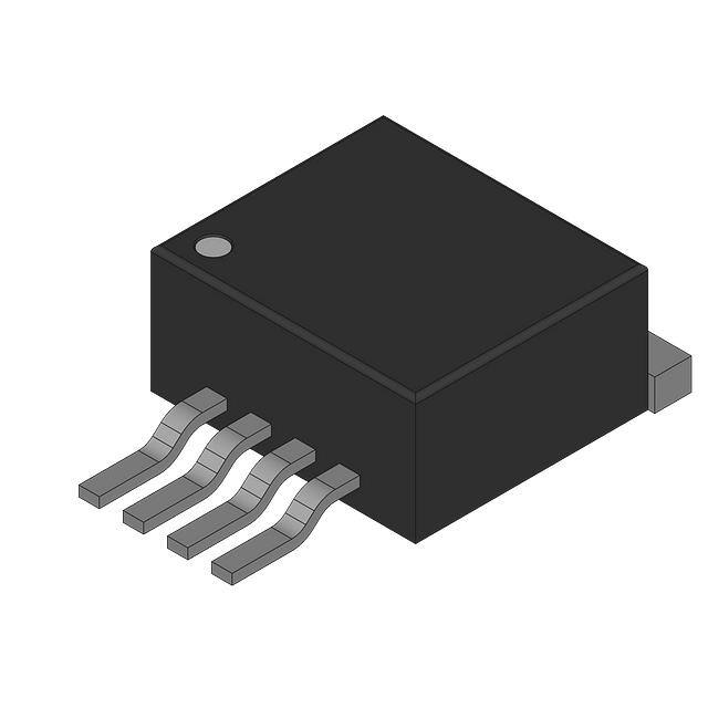
PG-TO252-5-11
Reduced switching losses
Optimized for EMC - low emission, high immunity
Optimized for PWM frequencies of approx. 100Hz
3.3V and 5V compatible logic inputs
Advanced analog load current sense signal supporting easy calibration for very high accuracy
Embedded diagnosis features (e.g. open load detection at ON and OFF)
Embedded protection functions (e.g. over current shutdown, over temperature shutdown)
Infineon® INTELLIGENT LATCH
Green Product (RoHS compliant)
AEC Qualified
Description
Embedded in a PG-TO252-5-11 package, the BTS50060-1TEA is a 6mΩ single channel Smart High-Side Power
Switch. It is based on Smart power chip on chip technology with a P-channel vertical power MOSFET, providing
protective and diagnostic functions. It is specially designed to drive loads in the harsh automotive environment.
Table 1
Product Summary
Parameter
Symbol
Values
Range of typical PWM frequencies
fPWM
RDS(ON)_150
VS(NOM)
IL(NOM)
IL(100Hz)
IS(OFF)
IL(SC)
-VS(REV)
0 Hz ... 1 kHz
Maximum On-state Resistance at Tj = 150 °C
Nominal Supply Voltage Range for Operation
Nominal Load Current (DC operation)
Typical Load Current at 100Hz
Typical Stand-by Current at Tj = 25 °C
Minimum short circuit current shutdown threshold
Maximum reverse battery voltage
12 mΩ
6 V … 19 V
16.5 A
13.5 A
5 µA
60 A
16 V
Type
Package
Marking
BTS50060-1TEA
PG-TO252-5-11
S50060A
Datasheet
High current PROFETTM
3
Rev. 1.2, 2011-09-01
�BTS50060-1TEA
Block Diagram
Embedded Protection functions
•
•
•
•
Infineon® INTELLIGENT LATCH - resettable latch resulting from protective switch OFF
Over current protection by short-circuit shutdown
Overload protection by over-temperature shutdown
Infineon® SMART CLAMPING
Embedded Diagnosis functions
•
•
•
•
Advanced analog load current sense signal with defined positive offset current; enabling load diagnosis, e.g.
open load at ON, overload
Providing defined fault signal
Open Load at OFF detection
Short-to-battery detection
2
Block Diagram
ESD + over voltage protection
Vs
A
Input circuit
RIN
Smart
Clamping
Diagnosis
IN
Gate
driver
&
Protection
Temp
IS
Figure 1
Sense output
OUT
BlockDiagram.emf
GND
Block Diagram of BTS50060-1TEA
For a Diagram of Diagnosis & Protection block, please see Figure 14.
Datasheet
High current PROFETTM
4
Rev. 1.2, 2011-09-01
�BTS50060-1TEA
Pin Configuration
3
Pin Configuration
3.1
Pin Assignment
IS
VS
4
5
IN
2
3 (OUT)
GND
1
OUT (TAB)
PinConfiguration .emf
Figure 2
Pin Configuration
3.2
Pin Definitions and Functions
Pin
Symbol
Function
1
GND
Ground; Ground connection for control chip.
2
IN
Input; Digital 3.3 V and 5 V compatible logic input; activates power switch if set to
HIGH level; Includes internal pull-down resistor RIN.
Tab; 31) OUT
Output; Protected high side power output
4
IS
Sense; Provides analog sense current signal and defined fault signal.
5
Vs
Supply Voltage; Positive supply voltage for Logic and Power Stage2)
1) Tab and pin 3 are internally connected. Pin 3 is cut.
2) PCB traces have to be designed to withstand maximum current occuring in the application.
3.3
Definition of Terms
Figure 3 shows all terms used for currents and voltages in this data sheet, with associated convention for positive
values.
VS
IS
IIN
VIN
VSIS
VS
IN
OUT
GND
IS
VSD
IL
IIS
V OUT
VIS
IGND
Terms.emf
Figure 3
Definition of currents and voltages
Datasheet
High current PROFETTM
5
Rev. 1.2, 2011-09-01
�BTS50060-1TEA
General Product Characteristics
4
General Product Characteristics
4.1
Absolute Maximum Ratings
Table 2
Absolute Maximum Ratings 1)
Tj = -40°C to 150°C; all voltages with respect to ground, positive current flowing into pin
(unless otherwise specified)
Parameter
Symbol
Values
Min.
T
y
p
.
Unit
Note /
Test Condition
Number
V
–
P_4.1
P_4.2
P_4.3
Max.
Supply voltages
Supply Voltage
Reverse Polarity Voltage on
pin GND, IS
Supply voltage for short
circuit protection
VS
|-VS(REV)|
-0.3
0
16
V
2) 3)
VBAT(SC)
0
28
V
4)
28
,
RECU = 20mΩ,
RCable = 6mΩ/m,
LCable = 1µH/m,
l = 0 or 5m,
see
Chapter 5.3.1
–
45
V
RI = 2 Ω 5) ,
RL = 1.0 Ω,
td = 400ms
P_4.4
nRSC1
–
1 E6
(Grade A)
–
4)6)
P_4.21
VIN
IIN
VIS
IIS
IGND
-0.3
6
V
–
P_4.5
-2
2
mA
t < 2min
P_4.6
-0.3
VS
V
–
P_4.7
-2
10
mA
–
P_4.8
-2
10
mA
–
P_4.9
-IL(SC)
IL(SC)
A
–
P_4.10
–
280
mJ
VS = 13.5V
IL(0) = 20A
Tj(0) = 150°C
P_4.11
Supply voltage for load dump VS(LD)
protection
Short circuit capability
Short circuit cycle capability
IN + IS + GND pin
Voltage at IN pin
Current through IN pin
Voltage at IS pin
Current through IS pin
Current through GND pin
Power stage
IL
Maximum energy dissipation EAS
Load current
for switching OFF an
inductive load
- single pulse
See Figure 4 and
Chapter 5.1.2
Maximum energy dissipation EAR
for switching OFF an
inductive load
- repetitive pulse
–
82
mJ
VS = 13.5V
IL(0) = 20A
Tj(0) = 105°C
P_4.13
See Figure 4 and
Chapter 5.1.2
Temperatures
Junction Temperature
Datasheet
High current PROFETTM
Tj
-40
150
6
°C
–
P_4.14
Rev. 1.2, 2011-09-01
�BTS50060-1TEA
General Product Characteristics
Table 2
Absolute Maximum Ratings (cont’d)1)
Tj = -40°C to 150°C; all voltages with respect to ground, positive current flowing into pin
(unless otherwise specified)
Parameter
Symbol
Values
Min.
T
y
p
.
Unit
Note /
Test Condition
Number
Max.
Dynamic temperature
increase while switching
ΔTj
–
60
K
–
P_4.15
Storage Temperature
Tstg
-55
150
°C
–
P_4.16
ESD Resistivity HBM
all Pins to GND
VESD1
-2
2
kV
HBM7)
P_4.17
ESD Resistivity HBM
VS vs. GND, VS vs. OUT,
OUT vs. GND
VESD2
-4
4
kV
HBM7)
P_4.18
ESD Resistivity CDM
all pins to GND
VESD3
-500
500
V
CDM8)
P_4.19
ESD Resistivity CDM
corner pins
VESD4
-750
750
V
CDM8)
P_4.20
ESD Susceptibility
1) Not subject to production test, specified by design.
2) In case of reverse polarity voltage on pin IN, IIN needs to be limited (see P_4.6) by external resistor RINPUT, see Figure 51.
3) In case of reverse polarity voltage, current through the OUT pin needs to be limited by external circuitry to prevent over
heating (see P_4.14). Power dissipation during reverse polarity voltage can be calculated by Equation (3). Please note,
build-in protection functions are not available during reverse polarity condition.
4) In accordance to AEC Q100-012 and AEC Q101-006.
5) VS(LD) is setup without the DUT connected to the generator per ISO 7637-1.
6) Test aborted after 1 E6 cycles.
7) ESD susceptibility, HBM according to ANSI/ESDA/JEDEC JS-001-2010
8) ESD susceptibility, Charged Device Model “CDM” EIA/JESD22-C101 or ESDA STM5.3.1
Datasheet
High current PROFETTM
7
Rev. 1.2, 2011-09-01
�BTS50060-1TEA
General Product Characteristics
1000
E A [mJ]
100
10
1
I L(0) [A]
10
100
E_AR (Tj(0) = 105°C)
E_AS (Tj(0) = 150°C)
Figure 4
Maximum energy dissipation for switching OFF an inductive load EA vs. load current
Notes
1. Stresses above the ones listed here may cause permanent damage to the device. Exposure to absolute
maximum rating conditions for extended periods may affect device reliability.
2. Integrated protection functions are designed to prevent IC destruction under fault conditions described in the
data sheet. Fault conditions are considered as “outside” normal operating range. Protection functions are not
designed for continuous repetitive operation.
Datasheet
High current PROFETTM
8
Rev. 1.2, 2011-09-01
�BTS50060-1TEA
General Product Characteristics
4.2
Functional Range
Table 3
Functional Range
Parameter
Symbol
Values
Min.
T
y
p
.
Unit
Note /
Test Condition
Number
Max.
Nominal Supply Voltage
Range for Operation
VS(NOM)
6
19
V
–
P_4.23
Extended Supply Voltage
Range for Operation
VS(EXT)
VS(UV)ON
28
V
1)2)
P_4.24
Extended Supply Voltage
Range for short dynamic
undervoltage swings
VS(DYN)
VS(UV)OFF
VS(UV)ON
V
1)2)3)
P_4.25
Junction Temperature
Tj
-40
150
°C
–
P_4.26
1) see Chapter 5.5, Undervoltage turn ON voltage and Undervoltage turn OFF voltage
2) In extended supply voltage range, the device is functional but electrical parameters are not specified.
3) Operation only if supply voltage was in range of VS(EXT) before undervoltage swing. Otherwise, device will stay OFF.
6V
13.5V
VS(UV)OFF
VS(UV)ON
VS(NOM)
V S(DYN)
19V
28V
VS(EXT)
VS
FunctionalRange.emf
Figure 5
Overview of functional ranges
Note: Within the functional or operating range, the IC operates as described in the circuit description. The electrical
characteristics are specified within the conditions given in the Electrical Characteristics table.
Datasheet
High current PROFETTM
9
Rev. 1.2, 2011-09-01
�BTS50060-1TEA
General Product Characteristics
4.3
Thermal Resistance
Note: This thermal data was generated in accordance with JEDEC JESD51 standards. For more information, go
to www.jedec.org.
Table 4
Thermal Resistance
Parameter
Symbol
Values
Unit
Note /
Test Condition
Number
Min.
Typ.
Max.
Thermal Resistance Junction to Case
RthJC
1)
–
1
1.1
K/W
–
P_4.27
Thermal Resistance Junction to Ambient - 2s2p
RthJA_2s2p1)
–
22
–
K/W
2)
P_4.29
1) Not subject to production test, specified by design.
2) Specified RthJA value is according to Jedec JESD51-2,-5,-7 at natural convection on FR4 2s2p board; The Product
(Chip+Package) was simulated on a 76.2 × 114.3 × 1.5 mm board with 2 inner copper layers (2 × 70 mm Cu, 2 × 35 mm
Cu). Where applicable a thermal via array under the exposed pad contacted the first inner copper layer.
Figure 6 and Figure 7 are showing the typical thermal impedance of BTS50060-1TEA mounted according to
Jedec JESD51-2,-5,-7 at natural convection on FR4 1s and 2s2p board. The product (chip + package) was
simulated on a 76.4 × 114.3 × 1.5 mm board with 2 inner copper layers (2× 70µm Cu, 2× 35µm Cu). Where
applicable, a thermal via array under the exposed pad contacted the first inner copper layer. The PCB layer
structure is shown in Figure 8. The PCB layout is shown in Figure 9.
���
���
����������������
���������
���������
����
��
����
� �
��������
� �
��������
��
�
�
���
����� ����
���
�
��
���
���
����� ����
����
� ����
��
Figure 6
������!
����������
����������
����������!
�����������
�����������
Typical transient thermal impedance
Zth(JA) = f(tP) for different cooling areas
Datasheet
High current PROFETTM
Figure 7
10
���
�
��
� ����
��
��� ����
Typical transient thermal impedance
Zth(JA) = f(tP) for PWM operation with
duty cycles D = t / tperiod on a 2s2p PCB
Rev. 1.2, 2011-09-01
�BTS50060-1TEA
General Product Characteristics
2s2p PCB
1s PCB
70µm
70µm
1.5mm
1.5mm
35µm
PCB 1s.emf
0.3mm
Figure 8
PCB 2s2p.emf
Cross section of 1s and 2s2p PCB used for ZthJA simulation
600mm²
300mm²
min
PCB front.emf
Figure 9
Front view of PCB layout used for ZthJA simulation
Datasheet
High current PROFETTM
11
Rev. 1.2, 2011-09-01
�BTS50060-1TEA
Functional Description
5
Functional Description
5.1
Power Stage
The power stage is built by a P-channel vertical power MOSFET (DMOS). The ON-state resistance RDS(ON)
depends on the supply voltage VS as well as the junction temperature Tj. Figure 25 shows the dependencies for
the typical ON-state resistance. The behavior in reverse polarity is described in Chapter 5.3.4. A HIGH signal at
the input pin (see Chapter 5.2) causes the power DMOS to switch ON. A LOW signal at the input pin causes the
power DMOS to switch OFF.
5.1.1
Switching a Resisitve Load
Defined slew rates for turn ON and OFF as well as edge shaping support PWM’ing of the load while achieving
lowest EMC emission at minimum switching losses. Figure 10 shows the typical timing when switching a resistive
load.
VIN
VIN(H),min
VIN(L),max
tON
VOUT
t
tOFF
tr
tf
90% VS
70% VS
(dV/dt)ON
(dV/dt)OFF
30% VS
10% VS
t
IL
t
P Loss
EON
EOFF
t
SwitchingResistiveLoad.emf
Figure 10
Switching a resistive load
5.1.2
Switching an Inductive Load - Infineon® SMART CLAMPING
When switching OFF inductive loads, the output voltage VOUT drops below ground potential due to the involved
inductance ( -diL/dt = -vL/L ; -VOUT ≅ -VL ). To prevent the destruction of the device due to high voltages, there is a
Datasheet
High current PROFETTM
12
Rev. 1.2, 2011-09-01
�BTS50060-1TEA
Functional Description
voltage clamp mechanism implemented that keeps the negative output voltage at a certain level (-VOUT = VS VSD(CL)). Please refer to Figure 1 and Figure 11 for details.
VOUT
VS
ON
OFF
VSD(CL)
t
IL
t
Figure 11
SwitchingInductance.emf
Switching an inductance
Nevertheless, the energy capability of the device is limited because the energy is converted into heat. That’s why
the maximum allowed load inductance is limited as well. Please see Figure 4 for limitations of energy and load
inductance.
For calculating the demagnization energy, Equation (1) may be used:
V S – V SD ( CL )
RL × IL ⎞
L
E A = V SD ( CL ) × ------ × -------------------------------× ln ⎛ 1 + ---------------------------------+I
⎝
RL
RL
VSD ( CL ) – VS⎠ L
(1)
The equation can be simplified under the assumption of RL = 0 Ω to:
V SD ( CL )
2
1
E A = --- × L × IL × -------------------------------2
V SD ( CL ) – V S
(2)
The BTS50060-1TEA provides Infineon® SMART CLAMPING functionality. To optimize the energy capability for
single and parallel operation, the clamp voltage VSD(CL) increases over the junction temperature Tj and load current
IL. Figure 36 shows the dependency from Tj for the typical VSD(CL). Please refer also to Figure 14.
5.1.3
Switching a Capacitive Load
A capacitive load’s dominant characteristic is it’s inrush current. The BTS50060-1TEA can support inrush currents
up to IL(SC). If the inrush current reaches IL(SC), the device may detect a short circuit and switch OFF. For a
description of the short circuit protection mechanism, please refer to Chapter 5.3.1.
5.1.4
Inverse Load Current Operation
In case of a negative load current, e.g. caused by a load operating as a generator, the device can not block the
current flowing through the intrinsic body diode. See Figure 12. The power stage of the device can be switched
ON or stays ON as long as VIN = HIGH, reaching the same RDS(ON) as for positive load currents, if no fault condition
is detected. In case of fault condition, the logic of the device will switch OFF the power stage and supply a fault
signal IIS(fault). Since the device can not block negative load currents (even under fault conditions), it can not protect
itself from overload condition. In the application, overload conditions, e.g. over temperature, must not occur during
inverse load current operation.
Datasheet
High current PROFETTM
13
Rev. 1.2, 2011-09-01
�BTS50060-1TEA
Functional Description
VS
logic
-IL(inv)
GND
G
LOAD
OUT
Invers.emf
Figure 12
Inverse load current operation
5.2
Input Circuit
The input circuitry is compatible with 3.3 and 5V micro controllers. If VIN is set to VIN = VIN(H) (VIN = HIGH), the
device will turn ON. See Figure 10 for the timings. If VIN is set to VIN = VIN(L) (VIN = LOW), the power stage of the
device will be turned OFF. The input circuitry has a hysteresis ΔVIN. The input circuitry is compatible with PWM
applications. Figure 13 shows the electrical equivalent input circuitry. The logic of the BTS50060-1TEA stays
active for a delay time tRESET after the switch OFF signal.
IN
R IN
GND
Figure 13
InputCircuitry.emf
Input pin circuitry
Applying an input voltage of VIN > 20V (absolute maximum ratings exceeded!) may force the BTS50060-1TEA to
deactivate parts of the logic circuitry. This includes the undervoltage shutdown, the undervoltage restart delay, and
the analog sense function. In this case, also the short circuit shutdown threshold IL(SC) is set to typically 50A, and
the latch reset time tRESET is reduced to typically 200µs. To reset this behavior, set input voltage to VIN = LOW for
t>300µs.
Datasheet
High current PROFETTM
14
Rev. 1.2, 2011-09-01
�BTS50060-1TEA
Functional Description
5.3
Protection Functions
The BTS50060-1TEA provides embedded protective functions. Integrated protection functions are designed to
prevent the destruction of the IC from fault conditions described in the data sheet. Fault conditions are considered
as “outside” normal operating range. Protection functions are designed for neither continuous nor repetitive
operation.
In case of overload, high inrush currents, or short circuit to ground, the BTS50060-1TEA offers several protection
mechanisms. Figure 14 describes the functionality of the diagnosis and protection block.
Diagnosis & Protection
Undervoltage protection
delay = td(UV)
Vs
VS(UV)
no delay
Input
circuit
No Undervoltage
IN
&
No FAULT
Gate
driver
INTELLIGENT LATCH
timer reset
no delay
Q S
Temp
Tjt
Q R
1
delay = tRESET
Sense
output
≥1
I L(SC)
A
0
1
IIS(fault)
ENABLE
≥1
OUT
VOUT(OL)
R OUT(GND)
Open Load at OFF
DiagnosisProtection. emf
Figure 14
Diagram of Diagnosis & Protection block
5.3.1
Protection by Over Current Shutdown
The internal logic permanently monitors the load current IL. In the event of a load current exceeding the short circuit
shutdown threshold (IL>IL(SC)), the output will switch OFF with a latching behavior. During an over current
shutdown, an overshooting IL(SC)peak may occur, depending on the short circuit impedances. For the case the
device is in ON state while short circuit appears, the typical overshooting IL(SC)peak as a function of the steepness
of the short circuit current dISC/dt, see Chapter 6.2.3.
For a detailed description of the latching behavior, please see Chapter 5.3.3.
At lower supply voltages the current tripping level IL(SC) will decrease depending on the supply voltage. At VS =
4.7V, the current tripping level will be reduced to IL(SC)LV. Please refer to Figure 38 for typical current tripping level
IL(SC) as a function of the supply voltage VS.
Datasheet
High current PROFETTM
15
Rev. 1.2, 2011-09-01
�BTS50060-1TEA
Functional Description
5.3.2
Protection by Over Temperature Shutdown
The internal logic permanently monitors the junction temperature of the output stage. In the event of an over
temperature (Tj > Tjt) the output will immediately switch OFF with a latching behavior, see Chapter 5.3.3 for
details.
5.3.3
Infineon® INTELLIGENT LATCH
The BTS50060-1TEA provides Infineon® INTELLIGENT LATCH to avoid permanent resetting of a protective,
latched switch OFF caused by over current shutdown or over temperature shutdown) in PWM applications. To
reset a latched protective switch OFF the fault has to be acknowledged by commanding the input LOW for a
minimum duration of treset. See Figure 15 for details.
VIN
tRESET
over temperature /
short circuit
VOUT
t
tRESET
t
t
IIS
IIS(fault)
IIS(OFFSET)
latch
reset
reset t
latch
INTELLIGENTLATCH.emf
Figure 15
Infineon® INTELLIGENT LATCH - fault acknowledge and latch reset
5.3.4
Reverse Polarity Protection
Reverse polarity condition is the mix-up of the power supply connections of the entire application. This means,
application GND connector is connected to positive supply voltage, while Vs pin is connected to negative supply
voltage or ground potential. See Figure 16 and Figure 51.
VS
-VS(rev)
R INPUT
logic
-IIN
R SENSE
-IL
RIS
GND
LOAD
OUT
Revers.emf
Figure 16
Reverse polarity condition
Datasheet
High current PROFETTM
16
Rev. 1.2, 2011-09-01
�BTS50060-1TEA
Functional Description
Under reverse polarity condition, the output stage can not block a current flow. It will conduct a load current via
the intrinsic body diode. The current through the output stage has to be limited either by the load itself or by
external circuitry, to avoid over heating of the power stage. Power losses in the power stage during reverse polarity
condition can be calculated by Equation (3):
P rev = ( – I L ( rev ) ) × ( – V SD ( rev ) )
(3)
Additionally, the current into the logic pins has to be limited to the maximum current described in Chapter 4.1 with
an external resistors. Figure 51 shows a typical application. Resistors RINPUT and RSENSE are used to limit the
current in the logic of the device and in the ESD protection stage. The recommended value for RINPUT = RSENSE =
10kΩ. As long as |-VS(rev)| < 16V, the current through the GND pin of the device is blocked by an internal diode.
5.3.5
Protection during Loss of Ground
In case of loss of the module ground or device ground connection (GND pin) the device protects itself by
automatically turning OFF (when it was previously ON) or remains OFF (even if the load remains connected to
ground), regardless if the input is driven HIGH or LOW. In case GND recovers the device may need a reset via
the IN pin to return to normal operation.
5.3.6
Protection during Loss of Load or Loss of VS Condition
In case of loss of load with charged primary inductances the maximum supply voltage has to be limited. It is
recommended to use a Z-diode, a varistor (VZa < 40V) or VS clamping power switches with connected loads in
parallel.
In case of loss of a charged inductive load, disturbances on pin OUT may require a reset on IN pin for the device
to regain normal operation.
In case of loss of VS connection with charged inductive loads, a current path with load current capability has to be
provided, to demagnetize the charged inductances. It is recommended to use a diode, a Z-diode or a varistor
(VZb < 16V, VZL + VD < 16V).
For higher clamp voltages currents through all pins have to be limited according to the maximum ratings. Please
see Figure 17 and Figure 18 for details.
GND
OUT
LOAD
logic
LOAD
GND
OUT
Smart
Clamping
VZa
VS
Smart
Clamping
VZb
logic
VS
VD
VZL
LossOfVs.emf
Figure 17
Loss of VS
Datasheet
High current PROFETTM
17
Rev. 1.2, 2011-09-01
�BTS50060-1TEA
Functional Description
VS
logic
OUT
LOAD
VZa
Smart
Clamping
VZb
GND
LossOfLoad.emf
Figure 18
Loss of load
5.3.7
Protection during ESD or Over Voltage Condition
All logic pins have ESD protection. A dedicated clamp mechanism protects the logic IC against transient over
voltages. See Figure 19 for details.
VS
ESD protection
IS
V Z(IC)
OUT
Over voltage
protection
IN
GND
Figure 19
OverVoltageProtection.emf
Over voltage protection
In the case (VS > max VS(SC))&(VS < VSD(CL)), the output transistor is still operational and follows the input.
Parameters are no longer warranted and lifetime is reduced compared to normal mode. This specially impacts the
short circuit robustness, as well as the maximum energy EAS the device can handle.
The BTS50060-1TEA provides Infineon® SMART CLAMPING functionality, which suppresses non nominal over
voltages by actively clamping the over voltage across the power stage and the load. This is achieved by controlling
the clamp voltage VSD(CL) depending on the junction temperature Tj and the load current IL. See Figure 14 for
details. Please refer also to Chapter 5.1.2.
Datasheet
High current PROFETTM
18
Rev. 1.2, 2011-09-01
�BTS50060-1TEA
Functional Description
5.4
Diagnosis Functions
For diagnosis purpose, the BTS50060-1TEA provides an advanced analog sense signal at the pin IS. For an
overview of the diagnosis functions, you may have a look at Figure 14 “Diagram of Diagnosis & Protection
block”.
5.4.1
Sense Output
The current sense output is a current source driving a signal IIS proportional to the load current (see Equation (5))
as long as no “hard” failure mode occurs (short circuit to GND / over temperature) and VSIS = VS - VIS > 3V. It is
activated and deactivated by the input signal. Usually, in the application a pull-down resistor RIS is connected
between the current sense pin IS and GND pin. A typical value is RIS = 1.0 kΩ. Figure 51 shows a simplified
application setup.
Table 5 is giving a quick reference for the logic / analog state of the IS pin during device operation.
In case a short circuit or an over temperature condition is detected, the sense output is supplying a fault signal
IIS(fault). The fault signal is reset by an input signal being LOW for t > tRESET. As long as an open load, short-to-VS
or inverse operation is detected while the device is in OFF state, the sense output also supplies the fault signal
IIS(fault). The timings and logic of the IS pin is described in Figure 20. During output turning ON or OFF, the sense
signal is invalid.
Table 5
Truth Table for Sense Signal
Operation mode
Normal operation
Input level
Output level
Sense output
LOW for t > tRESET
VOUT = VS - RDS(ON) * IL
VOUT ~ GND
(VOUT < VOUT(OLL))
HIGH
VOUT > VS
IIS = (IL / kIS) + IIS(OFFSET)
IIS = IIS(OFFSET)
Z3) (IIS = IIS(LL))
IIS ≤ IIS(OFFSET)
IIS = IIS(OFFSET)
IIS = IIS(FAULT)
IIS = IIS(FAULT)
HIGH
1)
LOW 2) for t < tRESET
Inverse operation
LOW for t < tRESET
LOW for t > tRESET
After short circuit to GND or HIGH or
over temperature detection LOW for t < tRESET
VOUT ~ GND
LOW for t > tRESET
Short circuit to VS
HIGH
Z (IIS = IIS(LL))
VOUT = VS
LOW for t < tRESET
LOW for t > tRESET
Open load
HIGH
LOW for t < tRESET
VOUT = VS
VOUT > VOUT(OLH)4)
LOW for t > tRESET
1)
2)
3)
4)
IIS ≤ IIS(OFFSET)
IIS = IIS(OFFSET)
IIS = IIS(FAULT)
IIS ≤ IIS(OFFSET)
IIS = IIS(OFFSET)
IIS = IIS(FAULT)
HIGH: VIN = VIN(H)
LOW: VIN = VIN(L)
Z: High impedance
Can be achieved e.g. with external pull up resistor ROL, see Figure 51.
Datasheet
High current PROFETTM
19
Rev. 1.2, 2011-09-01
�BTS50060-1TEA
Functional Description
VIN
t
tRESET
IL
tsIS(ON)
IIS
t
tsIS (OFF)
90% (IIS static - IIS(OFFSET))
tsIS(LC)
tsIS (LC)
10% (IIS static - IIS(OFFSET))
IIS (OFFSET)
t
Figure 20
CurrentSenseTiming .emf
Sense output timing
Figure 21 shows the current sense as a function of the load current in the power DMOS. The curves represent
the minimum and maximum values for the sense current, as well as the ideal sense current, assuming an ideal kIS
factor value as well as an ideal IIS(OFFSET).
10
�
max I IS(fault)
8
typ I IS(fault)
��!
�./�� #$
� #$�����
I IS [mA]
min I IS(fault)
6
max I IS
typ I IS
4
�
�-��� #$
min I IS
����� #$
max I L(SC)
2
�./�� #$%&''$*+,
��!
typ I L(SC)
�-��� #$%&''$*+,
min I L(SC)
0
����� #$%&''$*+,
�
0
Figure 21
20
40
60
I L [A]
80
100
�
!
��
�!
� "����
Sense current as a function of the load current (VSIS > 3V)
The sense current can be calculated out of the load current by the following Equation (4):
I IS = --1- × IL + IIS ( OFFSET )
k IS
(4)
Or, vice versa, the load current can be calculated out of the sense current by following Equation (5):
I L = k IS × ( I IS – I IS ( OFFSET ) )
Datasheet
High current PROFETTM
20
(5)
Rev. 1.2, 2011-09-01
�BTS50060-1TEA
Functional Description
For definition of kIS, the following Equation (6) is used:
IL1 –I L2
k IS = -------------------------------------------IIS ( I L1 ) –I IS ( IL2 )
(6)
IL1 and IL2 are two different load currents, IIS(IL1) and IIS(IL2) are the corresponding sense currents.
5.4.2
Enhancing Accuracy of the Sense Output by End of Line Calibration
For some applications it may be necessary to measure the load current with very high accuracy. To increase the
device accuracy, different methods can be used, e.g. single point calibration or dual point calibration.
The variance of the sense current at a certain load current depends on the variance of the factor kIS as well as on
the variance of the offset current IIS(OFFSET). The temperature variance of the factor kIS over the temperature range
is described with the parameter ΔkIS,Temp.
Δk IS ( Temp ) = max [ k IS ( – 40°C ) – k IS ( 25°C ) ; k IS ( 150°C ) – k IS ( 25°C ) ]
(7)
The variance of the sense current offset over the temperature range is defined as shown in Equation (8):
Δ I IS ( OFFSET ) = max [
5.4.3
IIS ( OFFSET ) ( –40°C ) – I IS ( OFFSET ) ( 25°C ) ; I IS ( OFFSET ) ( 150°C ) – IIS ( OFFSET ) ( 25°C ) ]
(8)
Short-to-Battery detection / Open Load Detection in OFF state
The BTS50060-1TEA provides open load diagnosis in OFF state. This is achieved by monitoring the OUT voltage.
The open load at OFF diagnosis is activated if VIN = LOW for t > tRESET. An open load or short-to-battery is detected
if VOUT > VOUT(OLH). To provoke this condition during Open Load, it may be necessary to use an external pull up
resistor ROL (see Figure 51). In case of detecting a shorted load to battery, open load, or inverse operation in OFF
state, the pin IS provides a defined fault current IIS(fault). If VOUT drops below VOUT(OLL), or VIN is set to HIGH, the
fault signal is removed. Figure 22 shows the behavior of the open load at OFF diagnosis. Figure 49 and
Figure 50 provide the typical behavior of VOUT(OLH) and VOUT(OLL) as a function of the supply voltage and junction
temperature. The device internally connects OUT with GND pin with an effective resistor ROUT(GND). In case the
application provides high leakage current outside of the BTS50060-1TEA between Vs and OUT, it may be
necessary to use an external resistor RL_OL to disable open load detection. Figure 51 gives an example of external
circuitry for enabling / disabling open load detection in OFF state.
Datasheet
High current PROFETTM
21
Rev. 1.2, 2011-09-01
�BTS50060-1TEA
Functional Description
VOUT
VOUT(OLH)
VOUT(OLL)
ΔVOUT(OL)
t
IIS
IIS(FAULT)
IIS(LL)
t
OpenLoad_at_OFF.emf
Figure 22
Open load detection in OFF state
5.5
Undervoltage Shutdown & Restart
The BTS50060-1TEA switches OFF whenever VS drops below VS(UV)OFF. The device restarts automatically after
the supply voltage increases to a sufficient level (VS > VS(UV)ON) and a delay time of tdelay(UV), if the input pin IN is
HIGH. Please see Figure 23 for details. The fault signal is reset if VS is below VS(UV) for more than typ. 70µs.
VIN
HIGH
t
VS
VS(UV)ON
VS(UV)OFF
ΔV S(UV)
t
VOUT
ON
tdelay(UV)
Z
t
Undervoltage.emf
Figure 23
Undervoltage shutdown and restart
Datasheet
High current PROFETTM
22
Rev. 1.2, 2011-09-01
�BTS50060-1TEA
Electrical Characteristics BTS50060-1TEA
6
Electrical Characteristics BTS50060-1TEA
6.1
Electrical Characteristics Table
Table 6
Electrical Characteristics: BTS50060-1TEA
VS = 6V to 19V, Tj = -40°C to 150°C, all voltages with respect to ground, positive current flowing into pin
(unless otherwise specified)
Parameter
Symbol
Values
Min.
Typ.
Max.
Unit
Note /
Test Condition
Number
VIN = LOW for
t > tRESET,
VS = 13.5V,
Tj = 25°C
VOUT < VOUT(OLL)
VIN = LOW for
t > tRESET,
VS = 13.5V,
Tj = 85°C
VOUT < VOUT(OLL)
VIN = LOW for
t > tRESET,
VS = 13.5V,
Tj = 150°C
VOUT < VOUT(OLL),
VIN = HIGH
t > tON
VIN = LOW for
t > tRESET,
VOUT > VOUT(OLH)
P_6.1
Operating currents
Standby current for whole
device with load
Tj = 25°C
IS(OFF)_251)
–
5
8
µA
Standby current for whole
device with load
Tj = 85°C
IS(OFF)_851)
–
5
8
µA
Standby current for whole
device with load
Tj = 150°C
IS(OFF)_150
–
20
60
µA
Ground current during ON
IGND(ON)
–
3
5
mA
Supply current during open
load detection in OFF state
IS(OL)1)
–
12
15
mA
On-State Resistance
RDS(ON)_251)
–
6.8
–
mΩ
On-State Resistance
RDS(ON)_150
–
10
12
mΩ
On-State Resistance
RDS(8V)_251)
–
8
–
mΩ
On-State Resistance
RDS(8V)_1501)
–
11.5
15
mΩ
P_6.2
P_6.3
P_6.4
P_6.5
Power stage
Datasheet
High current PROFETTM
23
VIN = HIGH,
Tj = 25 °C,
VS = 13.5V,
IL = +/-13.5A
VIN = HIGH,
Tj = 150 °C,
VS = 13.5V,
IL = +/-13.5A
VIN = HIGH,
Tj = 25 °C,
VS = 8V,
IL = +/-13.5A
VIN = HIGH,
Tj = 150 °C,
VS = 8V,
IL = +/-13.5A
P_6.6
P_6.7
P_6.8
P_6.9
Rev. 1.2, 2011-09-01
�BTS50060-1TEA
Electrical Characteristics BTS50060-1TEA
Table 6
Electrical Characteristics: BTS50060-1TEA (cont’d)
VS = 6V to 19V, Tj = -40°C to 150°C, all voltages with respect to ground, positive current flowing into pin
(unless otherwise specified)
Parameter
Symbol
Values
1)
Unit
Note /
Test Condition
Number
VIN = HIGH,
Tj = 25 °C,
VS = 4.7V,
IL = +/-13.5A
VIN = HIGH,
Tj = 150 °C,
VS = 4.7V,
IL = +/-13.5A
VIN = LOW,
IL = -13.5A
P_6.10
Min.
Typ.
Max.
–
10.5
–
mΩ
On-State Resistance at low
supply voltage
RDS(UV)_25
On-State Resistance at low
supply voltage
RDS(UV)_150
–
19
25
mΩ
Body diode forward voltage
drop2)
-VSD(rev)1)
300
600
1000
mV
P_6.11
P_6.12
(see Figure 12
and Figure 16)
Output leakage current3)
IL(OFF)_251)
–
0.1
1
µA
Output leakage current
IL(OFF)_851)
–
0.1
1
µA
Output leakage current
IL(OFF)_150
–
1
60
µA
0.12
0.18
0.36
V/µs
0.12
0.18
0.36
V/µs
-0.15
-
0.15
V/µs
–
80
130
µs
–
100
150
µs
-70
-20
30
µs
30
60
90
µs
P_6.22
Tj = 25°C,
VIN = LOW,
VOUT = 0V
Tj = 85°C,
VIN = LOW,
VOUT = 0V
Tj = 150°C,
VIN = LOW,
VOUT = 0V
P_6.13
RL = 1Ω,
VS = 13.5V
P_6.16
P_6.14
P_6.15
Switching a resistive load
Slew rate 30% to 70% VS
Slew rate 70% to 30% VS
Slew rate matching
(dV/dt)ON - |(dV/dt)OFF|
Turn ON time to 90% VS
Turn OFF time to 10% VS
Turn ON/OFF matching
Turn ON rise time 10% to
90% VS
(dV/dt)ON
-(dV/dt)OFF
ΔdV/dt
tON
tOFF
tON-tOFF
tr
(see Figure 10
for definitions and
Figure 29 to
Figure 35 for
parameter
dependencies)
P_6.17
P_6.18
P_6.19
P_6.20
P_6.21
Turn OFF fall time 90% to
10% VS
tf
30
60
90
µs
P_6.23
Switch ON energy
EON1)
EOFF1)
1.1
2.4
3.6
mJ
P_6.24
1.1
2.4
3.6
mJ
P_6.25
Source to Drain Smart
Clamping voltage4)
VSD(CL)_251)
32
40
–
V
Source to Drain Smart
Clamping voltage
VSD(CL)_1501)
40
48
–
V
Switch OFF energy
Switching an inductive load
Tj = 25°C,
IL = 40mA,
Tj = 150°C,
IL = 13.5A,
P_6.26
P_6.27
Input circuitry
Datasheet
High current PROFETTM
24
Rev. 1.2, 2011-09-01
�BTS50060-1TEA
Electrical Characteristics BTS50060-1TEA
Table 6
Electrical Characteristics: BTS50060-1TEA (cont’d)
VS = 6V to 19V, Tj = -40°C to 150°C, all voltages with respect to ground, positive current flowing into pin
(unless otherwise specified)
Parameter
Symbol
Values
Unit
Note /
Test Condition
Number
Min.
Typ.
Max.
VIN(L)
VIN(H)
ΔVIN1)
RIN
-0.3
–
0.8
V
–
P_6.28
2.0
–
6
V
–
P_6.29
–
200
–
mV
–
P_6.30
50
100
200
kΩ
–
P_6.31
Short circuit shutdown
threshold
IL(SC)
60
75
95
A
8V < VS < 19V
P_6.32
Short circuit shutdown
threshold at low supply
voltage
IL(SC)LV1)
10
–
IL(SC)
A
4.7V < VS < 8V
P_6.33
Thermal shutdown
temperature
Tjt
150
1751)
2001)
°C
–
P_6.34
Latch reset time
tRESET1)
40
55
80
ms
P_6.35
0
0.5
1.0
mA
VIN = LOW
6V < VS < 28V
VS = VS(EXT),
LOW level input voltage
HIGH level input voltage
Input voltage hysteresis
Input pull down resistor
Protection
Output leakage current while IOUT(GND)1)
GND disconnected5)
Over voltage protection of
logic IC
VZ(IC)
P_6.40
GND pin
disconnected
45
50
–
V
10.5
13
15
k
IGND = 5mA
P_6.41
Sense Output
Sense current steepness
(reciprocal)
kIS
kIS temperature variance
ΔkIS(Temp)1)
Sense current
IL = IL1
IIS(L1)
Sense current offset
IIS(OFFSET)
ΔIIS(OFFSET)
Sense current offset
temperature variance
see Equation (6) P_6.42
-2
0
+2
0.95
1.28
1.88
mA
50
240
600
µA
IL1 = 13.5A,
IL2 = 0A,
VS - VIS > 3V
IL = 13.5A,
VS - VIS > 3V
VS - VIS > 3V
-100
0
100
µA
see Equation (8) P_6.47
%
P_6.43
P_6.44
P_6.46
1)
Leakage Current at sense
output
IIS(LL)
0
0.1
1
µA
VIN = LOW for
t > tRESET,
VOUT < VOUT(OLL)
P_6.48
Fault signal current at sense
output
IIS(fault)
6.5
7.5
9
mA
6)
P_6.49
Current sense settling time
for turn ON to 90% IIS
tsIS(ON)1)
0
90
300
µs
Current sense settling time
for turn OFF to 10% IIS
tsIS(OFF)1)
0
110
300
µs
Current sense settling time
matching
tsIS(ON)tsIS(OFF)1)
-70
-20
30
µs
Datasheet
High current PROFETTM
25
VS - VIS > 3V
VS = 13.5V,
RL = 1.0Ω,
RIS = 1.0kΩ,
CSENSE < 100pF,
See Figure 20
P_6.50
P_6.51
P_6.52
Rev. 1.2, 2011-09-01
�BTS50060-1TEA
Electrical Characteristics BTS50060-1TEA
Table 6
Electrical Characteristics: BTS50060-1TEA (cont’d)
VS = 6V to 19V, Tj = -40°C to 150°C, all voltages with respect to ground, positive current flowing into pin
(unless otherwise specified)
Parameter
Current sense settling time
after changes of the load
current IL
Symbol
tsIS(LC)
Values
1)
Min.
Typ.
Max.
0
1
2
Unit
Note /
Test Condition
Number
µs
VIN = HIGH,
IL = 1A ↔ 50A
RIS = 1.0kΩ,
CSENSE < 100pF,
P_6.53
See Figure 20
Turn ON current sense
tsIS(FAULT)
settling time to IIS(fault) in case
of short circuit
1)
0
100
250
µs
RIS = 1.0kΩ,
CSENSE < 100pF,
P_6.54
See Figure 15
Open load at OFF
5
5.5
6
V
VIN = LOW,
for t > tRESET,
VS = 13.5V,
P_6.55
4.5
5
5.5
V
see Figure 22,
Figure 49 and
Figure 50
P_6.56
Output voltage hysteresis for ΔVOUT(OL)1)
open load detection in OFF
state
–
500
–
mV
ROUT(GND)1)
–
150
–
kΩ
VOUT = 4.5V,
VIN = LOW,
for t > tRESET
P_6.63
–
4.4
4.7
V
VS increasing,
VIN = HIGH
VS decreasing,
VIN = HIGH
VS(UV)ON VS(UV)OFF,
VIN = HIGH
VIN = HIGH
P_6.58
Output voltage threshold for
open load detection in OFF
state
VOUT(OLH)
Output voltage threshold for VOUT(OLL)
resetting open load detection
in OFF state
Intrinsic output pull-down
resistance
P_6.57
Undervoltage shutdown and restart
Undervoltage turn ON voltage VS(UV)ON
Undervoltage turn OFF
voltage
VS(UV)OFF
–
4.1
4.4
V
Undervoltage turn ON/OFF
hysteresis
ΔVS(UV)1)
–
0.25
–
V
Undervoltage restart delay
time
tdelay(UV)
4
6
8
ms
1)
2)
3)
4)
5)
6)
P_6.59
P_6.60
P_6.61
Not subject to production test, specified by design
Please note - during ON state, the output voltage drop in inverse current operation is defined by VSD = RDS(ON) x IL
See Figure 27 for typical temperature dependency.
See Figure 36 for typical temperature dependency.
All pins disconnected except for VS and OUT
Valid after over temperature or short ciruit to ground until reset (t > tRESET, VIN = LOW, or undervoltage detection) or during
detection of open load in OFF state.
Datasheet
High current PROFETTM
26
Rev. 1.2, 2011-09-01
�BTS50060-1TEA
Electrical Characteristics BTS50060-1TEA
Parameter Dependencies
6.2.1
Power Stage
�!
��
��
��
�!
@
� �$%&B,���&
��
� $%&'',��;��
6.2
��
!
�
?
�
�
3!�
�
!�
���
�!�
�
� 7��9:�
tRESET
12
��
10
��
8
@
� "%&'',��;��
R DS(ON) [mOhm]
Figure 24
3!�
6
���
�!�
Typical ON state resistance RDS(ON) as a
function of the junction temperature Tj
VS = 13.5V, IL = 13.5A, VIN = HIGH
�
4
?
2
�
0
!�
� 7��9:�
�
0
Figure 26
5
10
15
20
V S [V]
25
30
3!�
Typical ON state resistance RDS(ON) as a Figure 27
function of the supply voltage VS
Tj = 25°C, IL = 13.5A, VIN = HIGH
Datasheet
High current PROFETTM
27
�
!�
� 7��9:�
���
�!�
Typ. output leakage current IL(OFF) as a
function of the junction temperature Tj
VS = 13.5V, VIN = LOW
Rev. 1.2, 2011-09-01
�BTS50060-1TEA
Electrical Characteristics BTS50060-1TEA
���!
�
���
��@
�
� ��