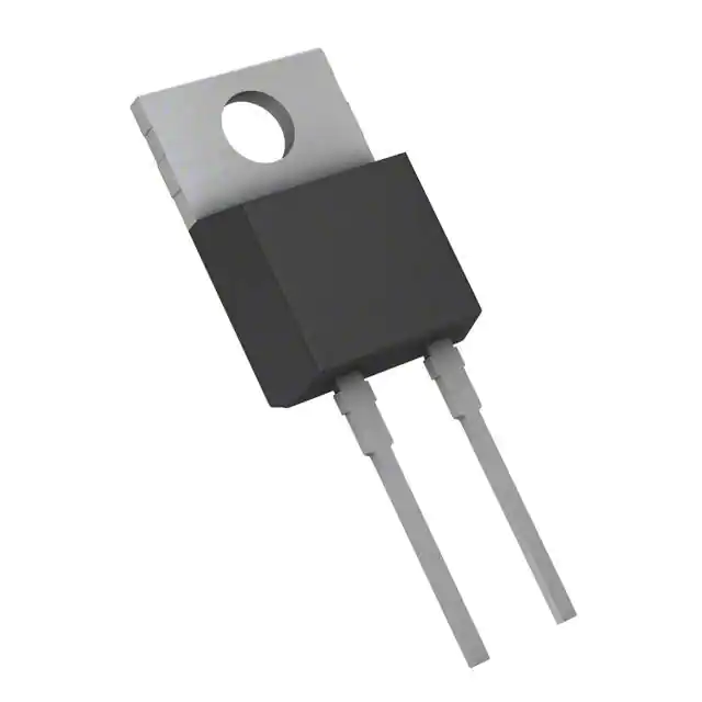
IDP15E60
Fast Switching Emitter Controlled Diode
Product Summary
Features
• 600V Emitter Controlled technology
VRRM
600
V
IF
15
A
VF
1.5
V
T jmax
175
°C
• Fast recovery
• Soft switching
• Low reverse recovery charge
• Low forward voltage
PG-TO220-2
• Easy paralleling
• Pb-free lead plating; RoHS compliant
• Halogen-free according to IEC61249-2-21
• Qualified according to JEDEC for target applications
Type
Package
IDP15E60
PG-TO220-2
Ordering Code
-
Marking
Pin 1
PIN 2
PIN 3
D15E60
C
A
-
Maximum Ratings, at Tj = 25 °C, unless otherwise specified
Parameter
Parameter
Symbol
Symbol
Repetitive
peak
reverse
voltage
Repetitive
peak
reverse
voltage
VRRM
VRRM
Continousforward
forward
current
Continuous
current
TTCC==25°C
25C
TTC ==90°C
90C
IF
IF
29.2
29.2
19.6
19.6
Surge non repetitive forward current
Surge non repetitive forward current
TC = 25C, tp = 10 ms, sine halfwave
I FSM
IFSM
6060
A
Maximum repetitive forward current
repetitive forward current
TMaximum
C = 25C, tp limited by tj,max, D = 0.5
IFRM
I FRM
4545
A
TC=25°C, tp limited by Tjmax, D=0.5
Power
dissipation
dissipation
TPower
C = 25C
TTCC==25°C
90C
PtotP t o t
83.3
47.2
83.3
C
Value
Value
600
600
Unit
Unit
VV
A
A
TC=25°C, tp=10 ms, sine halfwave
Tj
Operating
TC=90°C junction temperature
Tstg
Tj , T
stg
TS T S
Storage
temperature
Operating
and storage temperature
Soldering
temperature
Soldering temperature
1.6mm
(0.063 in.)
from (0.063
case for
10from
s case for 10s
wavesoldering,
1.6mm
in.)
Rev. 2.6
Page 1
-40…+175
47.2
-55...+150
-55...+175
260
260
WW
°C°C
°C
20131205
�IDP15E60
Thermal Characteristics
Symbol
Parameter
Values
Unit
min.
typ.
max.
Characteristics
Thermal resistance, junction - case
RthJC
-
-
1.8
Thermal resistance, junction - ambient, leaded
RthJA
-
-
62
SMD version, device on PCB:
RthJA
-
-
62
-
35
-
@ min. footprint
@ 6 cm 2 cooling area
1)
K/W
Electrical Characteristics, at Tj = 25 °C, unless otherwise specified
Parameter
Symbol
Values
min.
typ.
Unit
max.
Static Characteristics
IR
Reverse leakage current
μA
V R=600V, Tj=25°C
-
-
50
V R=600V, Tj=150°C
-
-
1250
VF
Forward voltage drop
V
IF=15A, T j=25°C
-
1.5
2
IF=15A, T j=150°C
-
1.5
-
1Device on 40mm*40mm*1.5mm epoxy PCB FR4 with 6cm² (one layer, 70 μm thick) copper area for drain
connection. PCB is vertical without blown air.
Rev. 2.6
Page 2
20131205
�IDP15E60
Electrical Characteristics, at Tj = 25 °C, unless otherwise specified
Symbol
Parameter
Values
min.
typ.
Unit
max.
Dynamic Characteristics
t rr
Reverse recovery time
ns
V R=400V, IF=15A, diF/dt=1000A/μs, Tj=25°C
-
87
-
V R=400V, IF=15A, diF/dt=1000A/μs, Tj=125°C
-
124
-
V R=400V, IF=15A, diF/dt=1000A/μs, Tj=150°C
-
131
-
I rrm
Peak reverse current
A
V R=400V, IF = 15A, diF/dt=1000A/μs, Tj =25°C
-
13.7
-
V R=400V, IF =15A, diF/dt=1000A/μs, T j=125°C
-
16.4
-
V R=400V, IF =15A, diF/dt=1000A/μs, T j=150°C
-
19.3
-
Q rr
Reverse recovery charge
nC
V R=400V, IF=15A, diF/dt=1000A/μs, Tj=25°C
-
595
-
V R=400V, IF =15A, diF/dt=1000A/μs, T j=125°C
-
995
-
V R=400V, IF =15A, diF/dt=1000A/μs, T j=150°C
-
1104
-
V R=400V, IF=15A, diF/dt=1000A/μs, Tj=25°C
-
3.6
-
V R=400V, IF=15A, diF/dt=1000A/μs, Tj=125°C
-
4.3
-
V R=400V, IF=15A, diF/dt=1000A/μs, Tj=150°C
-
4.5
-
S
Reverse recovery softness factor
Rev. 2.6
Page 3
20131205
�IDP15E60
1 Power dissipation
2 Diode forward current
Ptot = f (TC)
IF = f(TC)
parameter: Tj ≤ 175 °C
parameter: Tj≤ 175°C
90
30
W
A
60
20
IF
P tot
70
50
15
40
30
10
20
5
10
0
25
50
75
100
125
0
25
175
°C
50
75
100
125
TC
175
°C
TC
3 Typ. diode forward current
4 Typ. diode forward voltage
IF = f (VF)
VF = f (Tj)
50
2
V
30A
A
1.8
VF
IF
1.7
30
20
-55°C
25°C
100°C
150°C
1.6
1.5
15A
1.4
1.3
7.5A
10
1.2
1.1
0
0.5
1
1.5
2.5
V
VF
Rev. 2.6
Page 4
1
-60
-20
20
60
100
160
°C
Tj
20131205
�IDP15E60
5 Typ. reverse recovery time
6 Typ. reverse recovery charge
trr = f (diF/dt)
Qrr =f(diF/dt)
parameter: V R = 400V, T j = 125°C
parameter: VR = 400V, Tj = 125 °C
500
1450
ns
nC
400
30A
1250
Qrr
trr
350
30A
15A
7.5A
300
1150
15A
1050
250
950
200
850
150
7.5A
750
100
650
50
0
200
300
400
500
600
700
800
550
200
A/μs 1000
di F/dt
300
400
500
600
700
800
A/μs 1000
diF/dt
7 Typ. reverse recovery current
8 Typ. reverse recovery softness factor
Irr = f (diF/dt)
S = f(diF /dt)
parameter: V R = 400V, T j = 125°C
parameter: VR = 400V, Tj = 125°C
11
18
A
16
30A
15A
7.5A
15
9
13
S
Irr
14
8
30A
12
7
11
15A
10
6
9
8
7,5A
5
7
6
4
5
4
200
Rev. 2.6
300
400
500
600
700
800
A/μs 1000
di F/dt
Page 5
3
200
300
400
500
600
700
800
A/μs 1000
diF/dt
20131205
�IDP15E60
9 Max. transient thermal impedance
ZthJC = f (tp)
parameter : D = t p/T
10 1
IDP15E60
K/W
ZthJC
10 0
10 -1
D = 0.50
0.20
0.10
0.05
10 -2
0.02
0.01
single pulse
10 -3 -7
10
10
-6
10
-5
10
-4
10
-3
10
-2
s
10
0
tp
Rev. 2.6
Page 6
20131205
�IDP15E60
Package Outline: TO220-2
Rev. 2.6
Page 7
20131205
�IDP15E60
Published by
Infineon Technologies AG
81726 Munich, Germany
81726 München, Germany
© 2009 Infineon Technologies AG
All Rights Reserved.
Published by
Legal Disclaimer
Infineon
Technologies AG
The information given in this document shall in no event be regarded as a guarantee of conditions or characteristics.
81726
Munich,
Germany
With respect to any
examples or hints given herein, any typical values stated herein and/or any information regarding
the2013
application
of the
device, Infineon
Technologies hereby disclaims any and all warranties and liabilities of any kind,
©
Infineon
Technologies
AG
including without limitation, warranties of non-infringement of intellectual property rights of any third party.
All Rights Reserved.
Information
For further information on technology, delivery terms and conditions and prices, please contact the nearest Infineon
Technologies Office (www.infineon.com).
Legal
Disclaimer
Warnings
Due
to
technical requirements,
components
may
contain
dangerous
substances.
on theoftypes
in
The information
given in this
document
shall
in no
event be
regardedForasinformation
a guarantee
conditions
or
question, please contact the nearest Infineon Technologies Office. Infineon Technologies components may be used in
characteristics.
With
respect
to
any
examples
or
hints
given
herein,
any
typical
values
stated
herein
and/or
life-support devices or systems only with the express written approval of Infineon Technologies, if a failure of such
any
information
regarding be
theexpected
application
of the
Technologies
and all
components
can reasonably
to cause
thedevice,
failure ofInfineon
that life-support
device orhereby
systemdisclaims
or to affectany
the safety
or effectiveness
that device
or system.
Life support
devices
or systems
are intended
to be implanted in the
human
warranties
and of
liabilities
of any
kind, including
without
limitation,
warranties
of non-infringement
of intellectual
body or to support and/or maintain and sustain and/or protect human life. If they fail, it is reasonable to assume that the
property
rights
third
party.may be endangered.
health of the
useroforany
other
persons
Information
For further information on technology, delivery terms and conditions and prices, please contact the nearest
Infineon Technologies Office (www.infineon.com).
Warnings
Due to technical requirements, components may contain dangerous substances. For information on the types
in question, please contact the nearest Infineon Technologies Office.
The Infineon Technologies component described in this Data Sheet may be used in life-support devices or
systems and/or automotive, aviation and aerospace applications or systems only with the express written
approval of Infineon Technologies, if a failure of such components can reasonably be expected to cause the
failure of that life-support, automotive, aviation and aerospace device or system or to affect the safety or
effectiveness of that device or system. Life support devices or systems are intended to be implanted in the
human body or to support and/or maintain and sustain and/or protect human life. If they fail, it is reasonable
to assume that the health of the user or other persons may be endangered.
Rev. 2.6
Page 8
20131205
�