IKFW40N65ES5
TRENCHSTOPTM�5�Advanced�Isolation
TRENCHSTOPTM�5�high�speed�soft�switching�IGBT�copacked�with�full�current
rated�RAPID�1�fast�and�soft�antiparallel�diode�in�fully�isolated�package
�
Features�and�Benefits:
C
High�speed�S5�technology�offering
•�High�speed�smooth�switching�device�for�hard�&�soft�switching
•�Very�Low�VCEsat,�1.35V�at�nominal�current
•�Plug�and�play�replacement�of�previous�generation�IGBTs
•�650V�breakdown�voltage
•�Low�gate�charge�QG
•�IGBT�copacked�with�full�rated�RAPID�1�fast�antiparallel�diode
•�Maximum�junction�temperature�175°C
•�Pb-free�lead�plating;�RoHS�compliant
•�Complete�product�spectrum�and�PSpice�Models:
http://www.infineon.com/igbt/
G
E
Applications:
•�Resonant�converters
•�Uninterruptible�power�supplies
•�Welding�converters
•�Mid�to�high�range�switching�frequency�converters
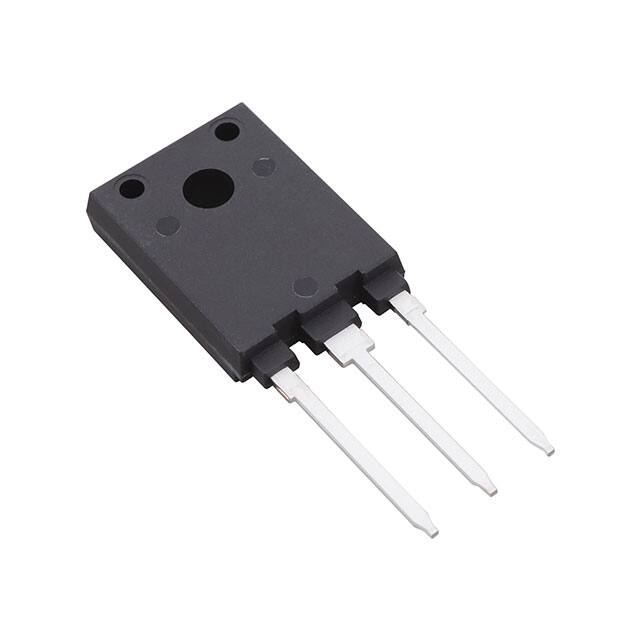
Fully isolated package TO-247
Product�Validation:
Qualified�for�industrial�applications�according�to�the�relevant�tests
of�JEDEC47/20/22
Key�Performance�and�Package�Parameters
Type
IKFW40N65ES5
Datasheet
www.infineon.com
VCE
IC
VCEsat,�Tvj=25°C
Tvjmax
Marking
Package
650V
30A
1.35V
175°C
K40EES5
PG-HSIP247-3-2
Please�read�the�Important�Notice�and�Warnings�at�the�end�of�this�document
V�2.1
2020-09-17
�IKFW40N65ES5
TRENCHSTOPTM�5�Advanced�Isolation
Table�of�Contents
Description . . . . . . . . . . . . . . . . . . . . . . . . . . . . . . . . . . . . . . . . . . . . . . . . . . . . . . . . . . . . . . . . . . . . . . . . 1
Table of Contents . . . . . . . . . . . . . . . . . . . . . . . . . . . . . . . . . . . . . . . . . . . . . . . . . . . . . . . . . . . . . . . . . . . 2
Maximum Ratings . . . . . . . . . . . . . . . . . . . . . . . . . . . . . . . . . . . . . . . . . . . . . . . . . . . . . . . . . . . . . . . . . . . 3
Thermal Resistance . . . . . . . . . . . . . . . . . . . . . . . . . . . . . . . . . . . . . . . . . . . . . . . . . . . . . . . . . . . . . . . . . 3
Electrical Characteristics . . . . . . . . . . . . . . . . . . . . . . . . . . . . . . . . . . . . . . . . . . . . . . . . . . . . . . . . . . . . . . 4
Electrical Characteristics Diagrams . . . . . . . . . . . . . . . . . . . . . . . . . . . . . . . . . . . . . . . . . . . . . . . . . . . . . 6
Package Drawing . . . . . . . . . . . . . . . . . . . . . . . . . . . . . . . . . . . . . . . . . . . . . . . . . . . . . . . . . . . . . . . . . . .12
Testing Conditions . . . . . . . . . . . . . . . . . . . . . . . . . . . . . . . . . . . . . . . . . . . . . . . . . . . . . . . . . . . . . . . . . .13
Revision History . . . . . . . . . . . . . . . . . . . . . . . . . . . . . . . . . . . . . . . . . . . . . . . . . . . . . . . . . . . . . . . . . . . .14
Disclaimer . . . . . . . . . . . . . . . . . . . . . . . . . . . . . . . . . . . . . . . . . . . . . . . . . . . . . . . . . . . . . . . . . . . . . . . . .15
Datasheet
2
V�2.1
2020-09-17
�IKFW40N65ES5
TRENCHSTOPTM�5�Advanced�Isolation
Maximum�Ratings
For�optimum�lifetime�and�reliability,�Infineon�recommends�operating�conditions�that�do�not�exceed�80%�of�the�maximum�ratings�stated�in�this�datasheet.
Parameter
Symbol
Collector-emitter�voltage,�Tvj�≥�25°C
VCE
DC�collector�current,�limited�by�Tvjmax
Th�=�25°C
Th�=�65°C
Th�=�65°C
IC
60.0
48.0
52.01)
Pulsed�collector�current,�tp�limited�by�Tvjmax
ICpuls
120.0
A
Turn off safe operating area
VCE�≤�650V,�Tvj�≤�175°C,�tp�=�1µs
-
120.0
A
Diode�forward�current,�limited�by�Tvjmax
Th�=�25°C
Th�=�65°C
IF
56.0
43.0
A
Diode�pulsed�current,�tp�limited�by�Tvjmax
IFpuls
120.0
A
Gate-emitter voltage
Transient�Gate-emitter�voltage�(tp�≤�10µs,�D�
很抱歉,暂时无法提供与“IKFW40N65ES5XKSA1”相匹配的价格&库存,您可以联系我们找货
免费人工找货- 国内价格 香港价格
- 1+71.060751+9.18874
- 30+41.0052330+5.30231
- 120+34.40440120+4.44877
- 510+29.56675510+3.82323
- 1020+28.062121020+3.62866