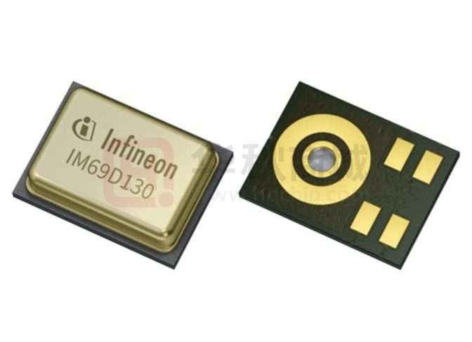
IM72D128V01
IP57 dust and water resistant digital PDM XENSIVTM MEMS microphone
Description
The IM72D128V01 is an ultra-high performance digital PDM MEMS microphone designed for applications which
require a very high SNR (low self-noise) and low distortion (high AOP) and which is also IP57 robust to dust and
water.
Best-in-class signal-to-noise ratio (SNR) of 72dB(A) enables far field and low volume audio pick-up. The flat
frequency response (20Hz low-frequency roll-off) and tight manufacturing tolerance improve performance of
multi-microphone (array) applications.
The digital microphone ASIC contains an extremely low-noise preamplifier and a high-performance sigma-delta
ADC. Different power modes can be selected in order to suit specific clock frequency and current consumption
requirements.
Each IM72D128V01 microphone is calibrated with an advanced Infineon calibration algorithm, resulting in low
sensitivity tolerances (± 1dB).
Features
•
•
•
•
•
Component level IP57 water and dust resistant
Dynamic range of 106dB
Acoustic overload point at 128dBSPL
Signal to noise ratio of 72dB(A) SNR
Digital PDM output
•
•
•
•
Flat frequency response with a low frequency rolloff at 20Hz
Package dimensions: 4mm x 3mm x 1.2mm
Omnidirectional pickup pattern
Power optimized modes determined by PDM
clock frequency
Typical applications
•
•
Active Noise Cancellation (ANC) headphones and
earphones
Devices with Voice User Interface (VUI)
- Smart speakers
- Home automation
- IOT devices
•
•
High quality audio capturing
- Laptops and tablets
- Conference systems
- Cameras and camcorders
Industrial or home monitoring with audio pattern
detection
Ordering information
Table 1
Ordering information
Product name
Package
Marking
Ordering code
IM72D128V01
PG-LLGA-5-3
I72D07
SP005738480
Datasheet
www.infineon.com
Please read the sections "Important notice" and "Warnings" at the end of this document
1.01
2022-05-05
�IM72D128V01
IP57 dust and water resistant digital PDM XENSIVTM MEMS microphone
Product validation
Product validation
Technology qualified for industrial applications.
Ready for validation in industrial applications according to the relevant tests of IEC 60747 and 60749 or
alternatively JEDEC47/20/22.
Block diagram
Figure 1
Block diagram
Environmental robustness
Infineon’s latest Sealed Dual Membrane MEMS technology delivers high ingress protection (IP57) at a
microphone level. The sealed MEMS design prevents water or dust from entering between membrane
and backplate, preventing mechanical blockage or electric leakage issues commonly observed in MEMS
microphones. Microphones built with the Sealed Dual Membrane technology can be used to create IP68
devices, requiring only minimal mesh protection.
Table 2
Environmental robustness
Test Standard
Test Condition
IP5x dust resistance1)
Arizona dust A4 coarse, vertical orientation , sound hole upwards, 10
cycles (15 minutes sedimentation, 6 sec blowing)
IPx7 water immersion2)
Temporary immersion of 1 meters for 30 minutes. Microphone tested
2 hours after removal
1
2
The number "5" stands for the dust ingress rating or the capacity to withstand the effects of fine, abrasive dust particles.
The "7" specifies the higher water immersion rating.
Datasheet
2
1.01
2022-05-05
�IM72D128V01
IP57 dust and water resistant digital PDM XENSIVTM MEMS microphone
Table of contents
Table of contents
Description . . . . . . . . . . . . . . . . . . . . . . . . . . . . . . . . . . . . . . . . . . . . . . . . . . . . . . . . . . . . . . . . . . . . . . . . . . . . 1
Features . . . . . . . . . . . . . . . . . . . . . . . . . . . . . . . . . . . . . . . . . . . . . . . . . . . . . . . . . . . . . . . . . . . . . . . . . . . . . . . 1
Typical applications . . . . . . . . . . . . . . . . . . . . . . . . . . . . . . . . . . . . . . . . . . . . . . . . . . . . . . . . . . . . . . . . . . . . 1
Ordering information . . . . . . . . . . . . . . . . . . . . . . . . . . . . . . . . . . . . . . . . . . . . . . . . . . . . . . . . . . . . . . . . . . .1
Product validation . . . . . . . . . . . . . . . . . . . . . . . . . . . . . . . . . . . . . . . . . . . . . . . . . . . . . . . . . . . . . . . . . . . . . 2
Block diagram . . . . . . . . . . . . . . . . . . . . . . . . . . . . . . . . . . . . . . . . . . . . . . . . . . . . . . . . . . . . . . . . . . . . . . . . . 2
Environmental robustness . . . . . . . . . . . . . . . . . . . . . . . . . . . . . . . . . . . . . . . . . . . . . . . . . . . . . . . . . . . . . .2
Table of contents . . . . . . . . . . . . . . . . . . . . . . . . . . . . . . . . . . . . . . . . . . . . . . . . . . . . . . . . . . . . . . . . . . . . . . . 3
1
Typical performance characteristics . . . . . . . . . . . . . . . . . . . . . . . . . . . . . . . . . . . . . . . . . . . . . . . . . . . . 4
2
Acoustic characteristics . . . . . . . . . . . . . . . . . . . . . . . . . . . . . . . . . . . . . . . . . . . . . . . . . . . . . . . . . . . . . . . . 6
3
3.1
3.2
3.3
3.4
3.5
Electrical characteristics and parameters . . . . . . . . . . . . . . . . . . . . . . . . . . . . . . . . . . . . . . . . . . . . . . . .7
Absolute maximum ratings . . . . . . . . . . . . . . . . . . . . . . . . . . . . . . . . . . . . . . . . . . . . . . . . . . . . . . . . . . . . . . .7
Electrical parameters . . . . . . . . . . . . . . . . . . . . . . . . . . . . . . . . . . . . . . . . . . . . . . . . . . . . . . . . . . . . . . . . . . . . 7
Electrical characteristics . . . . . . . . . . . . . . . . . . . . . . . . . . . . . . . . . . . . . . . . . . . . . . . . . . . . . . . . . . . . . . . . . 8
Audio DC offset . . . . . . . . . . . . . . . . . . . . . . . . . . . . . . . . . . . . . . . . . . . . . . . . . . . . . . . . . . . . . . . . . . . . . . . . . 9
Stereo PDM configuration . . . . . . . . . . . . . . . . . . . . . . . . . . . . . . . . . . . . . . . . . . . . . . . . . . . . . . . . . . . . . . . 10
4
Package information . . . . . . . . . . . . . . . . . . . . . . . . . . . . . . . . . . . . . . . . . . . . . . . . . . . . . . . . . . . . . . . . . . 11
5
Footprint and stencil recommendation . . . . . . . . . . . . . . . . . . . . . . . . . . . . . . . . . . . . . . . . . . . . . . . . .12
6
Packing information . . . . . . . . . . . . . . . . . . . . . . . . . . . . . . . . . . . . . . . . . . . . . . . . . . . . . . . . . . . . . . . . . . 13
7
Reflow soldering and board assembly . . . . . . . . . . . . . . . . . . . . . . . . . . . . . . . . . . . . . . . . . . . . . . . . . . 14
8
Reliability specifications . . . . . . . . . . . . . . . . . . . . . . . . . . . . . . . . . . . . . . . . . . . . . . . . . . . . . . . . . . . . . . 16
Revision history . . . . . . . . . . . . . . . . . . . . . . . . . . . . . . . . . . . . . . . . . . . . . . . . . . . . . . . . . . . . . . . . . . . . . . .17
Disclaimer . . . . . . . . . . . . . . . . . . . . . . . . . . . . . . . . . . . . . . . . . . . . . . . . . . . . . . . . . . . . . . . . . . . . . . . . . . . . 18
Datasheet
3
1.01
2022-05-05
�IM72D128V01
IP57 dust and water resistant digital PDM XENSIVTM MEMS microphone
Typical performance characteristics
1
Typical performance characteristics
Test conditions: VDD = 1.8V, fCLK = 3.072MHz, unless otherwise specified.
Sensitivity relative to 1kHz [dB]
Normalized Output Level [dB]
12
9
6
3
0
-3
-6
-9
-12
10
100
1000
10000
30
25
20
15
10
5
0
-5
-10
0
Frequency [Hz]
Figure 2
20
40
60
80
Frequency [kHz]
Typical amplitude response
Figure 3
90
Typical free field ultrasonic
response
10000
60
Group Delay [µs]
Phase Response [°]
75
45
30
15
0
1000
100
10
-15
-30
1
10
100
1000
10000
10
Frequency [Hz]
Figure 4
100
1000
10000
Frequency [Hz]
Typical phase response
Figure 5
Typical group delay
1
THD [%]
THD [%]
10
10
128dB SPL
1
126dB SPL
0.1
110dB SPL
0.1
0.01
90
95
100
105
110
115
120
125
100
130
Input Sound Pressure Level [dB]
Figure 6
Datasheet
1000
10000
Frequency [Hz]
Typical THD vs SPL
Figure 7
4
Typical THD vs frequency
1.01
2022-05-05
�IM72D128V01
IP57 dust and water resistant digital PDM XENSIVTM MEMS microphone
Typical performance characteristics
-110
1200
fclock = 4.800MHz
800
Spectral Noise Density
[dBFS/sqrt(Hz)]
1000
IDD [µA]
-115
fclock = 3.072MHz
fclock = 2.400MHz
fclock = 1.536MHz
600
400
fclock = 768kHz
200
-120
-125
-130
-135
-140
-145
-150
-155
-160
10.00
0
1.60
2.10
2.60
3.10
3.60
Figure 8
Datasheet
100.00
1000.00
10000.00
Frequency [Hz]
VDD [V]
Typical IDD vs VDD
Figure 9
5
Typical noise floor
(unweighted)
1.01
2022-05-05
�IM72D128V01
IP57 dust and water resistant digital PDM XENSIVTM MEMS microphone
Acoustic characteristics
2
Acoustic characteristics
Test conditions (unless otherwise specified in the table): VDD = 1.8V, fCLK = 3.072MHz, TA = 25°C, 55% R.H., audio
bandwidth 20Hz to 20kHz, select pin grounded, no load on DATA, Tedge = 9ns
Table 3
acoustic specifications
Parameter
Symbol
Sensitivity
S
Low Frequency Roll-off
Values
Min.
Typ.
Max.
-37
-36
-35
Note or Test Condition
dBFS
1kHz, 94dBSPL, all
operating modes
20
Hz
-3dB relative to 1kHz
High Frequency Flatness3)
19
kHz
+3dB relative to 1kHz
Resonance Frequency Peak3)
37
kHz
Signal to Noise fclock = 768kHz
Ratio
LFRO
Unit
SNR
fclock = 1.536MHz
68
fclock = 2.4MHz
Total
Harmonic
Distortion
72
fclock = 4.8MHz3)
71.5
Phase
Response
Directivity
Polarity
3
THD
0.5
126dBSPL
Acoustic
10% THD
Overload Point
Group Delay
71.5
fclock = 3.072MHz
94dBSPL
20Hz to 8kHz bandwidth,
A-Weighted
67
1.0
AOP
128
250Hz
60
600Hz
12
1kHz
7
4kHz
3.5
75Hz
20
1kHz
0.5
4kHz
-2
20Hz to 20kHz bandwidth,
dB(A) A-Weighted
%
Measuring 2nd to 5th
harmonics; 1kHz. all
operating modes
Measuring 2nd to 5th
dBSPL harmonics; 1kHz. all
operating modes
µs
°
Omnidirectional
Positive pressure increases density of 1's,
negative pressure decreases density of 1's in
data output
Parameter not subject to productive test. Verified by laboratory characterization / design.
Datasheet
6
1.01
2022-05-05
�IM72D128V01
IP57 dust and water resistant digital PDM XENSIVTM MEMS microphone
Electrical characteristics and parameters
3
Electrical characteristics and parameters
3.1
Absolute maximum ratings
Stresses at or above the listed maximum ratings may affect device reliability or cause permanent device
damage. Functional device operation at these conditions is not guaranteed.
Table 4
Absolute maximum ratings
Parameter
Symbol
Values
Min.
Voltage on any Pin
Unit
Max.
Vmax
3.6
V
Storage Temperature
TS
-40
125
°C
Ambient Temperature
TA
-40
85
°C
3.2
Electrical parameters
Table 5
Electrical parameters and digital interface input
Parameter
Symbol
Supply Voltage
VDD
Clock
Frequency
Range
fclock
Standby Mode
Note / Test Condition
Values
Unit
Note / Test Condition
Min.
Typ.
Max.
1.62
1.8
3.6
V
4)
350
kHz
5)
Low Power
Mode
450
768
850
kHz
Normal Mode
1.2
1.536
1.65
MHz
High
Performance
Mode
2.0
2.4
2.6
MHz
2.9
3.072
3.3
MHz
Ultrasonic
Mode
4.56
4.8
5.04
MHz
50
ms
VDD Ramp-up Time
Time until VDD ≥ VDD_min
Input Logic Low Level
VIL
-0.3
0.35xVDD
V
Input Logic High Level
VIH
0.65xVDD
VDD+0.3
V
13
ns
10% to 90%
40
60
%
fclock≤ 3MHz
48
52
%
fclock> 3MHz
200
pF
Clock Rise/Fall Time
Clock Duty Cycle
Output Load Capacitance on
DATA
4
5
Cload
A 1μF bypass capacitor shall be placed close to the microphone VDD pad to ensure best SNR performance.
Data pad is high impedance in standby mode.
Datasheet
7
1.01
2022-05-05
�IM72D128V01
IP57 dust and water resistant digital PDM XENSIVTM MEMS microphone
Electrical characteristics and parameters
3.3
Electrical characteristics
Test conditions (unless otherwise specified in the table): VDD = 1.8V, TA = 25°C, 55% R.H.
Table 6
General electrical characteristics
Parameter
Symbol
Values
Min.
Current
Clock Off Mode
Consumption
Standby Mode
Typ.
Iclock_off
Unit
Max.
1
Istandby
25
50
IDD
280
310
fclock = 1.536MHz
690
770
fclock = 2.4MHz
820
945
fclock = 3.072MHz
980
1120
fclock = 4.8MHz
900
1000
fclock = 768kHz
Short Circuit Current
Power Supply Rejection
1
20
PSR1k_NM
-80
PSR217_NM
-86
±0.2dB
sensitivity
accuracy
50
±0.5dB
sensitivity
accuracy
20
±0.2dB
sensitivity
accuracy
50
VOL
Output Logic High Level
VOH
0.7xVDD
Delay Time for DATA Driven
tDD
Delay Time for DATA High-Z7)
tHZ
No load on DATA
mA
Grounded DATA pin
100mVpp sine wave on
VDD swept from 200Hz to
20kHz.
dBFS(A) 100mVrms, 217Hz square
wave on VDD. A-weighted.
20
Output Logic Low Level
CLOCK pulled low
很抱歉,暂时无法提供与“IM72D128V01XTMA1”相匹配的价格&库存,您可以联系我们找货
免费人工找货- 国内价格 香港价格
- 1+20.132961+2.60466
- 10+15.7681310+2.03997
- 25+14.3496625+1.85646
- 50+13.3769550+1.73062
- 100+12.48082100+1.61468
- 250+11.75597250+1.52091
- 国内价格
- 10+16.28204
- 100+15.44372
- 250+14.69913
- 500+13.95975
- 国内价格
- 2+17.15680
- 10+16.28204
- 100+15.44372
- 250+14.69913
- 500+13.95975
- 国内价格 香港价格
- 5000+9.604455000+1.24256