Digital Multi-Phase Buck Controller
FEATURES
IR3536A
IR3538A
DESCRIPTION
6-phase & 8-phase dual output PWM Controller
Phases are flexibly assigned between Loops 1 & 2
Intel® VR12, AMD® 3.4MHz SVI/PVI & Memory
modes
The IR3536A and IR3538A are dual-loop digital multi-phase
buck controllers. The IR3536A drive up to 6 phases and the
IR3538A drives up to 8 phases. The IR3536A and IR3538A
are fully Intel® VR12 and AMD® SVI/PVI compliant on both
loops and provide a Vtt tracking function for DDR memory.
Overclocking & Gaming Mode with Vmax setting
Switching frequency from 200kHz to 1.2MHz per
phase
IR Efficiency Shaping Features including Variable
Gate Drive and Dynamic Phase Control
Programmable 1-phase or 2-phase for Light Loads
and Active Diode Emulation for Very Light Loads
IR Adaptive Transient Algorithm (ATA) on both loops
minimizes output bulk capacitors and system cost
Auto-Phase Detection with auto-compensation
Per-Loop Fault Protection: OVP, UVP, OCP, OTP, CFP
I2C/SMBus/PMBus system interface for telemetry
of Temperature, Voltage, Current & Power for
both loops
Non-Volatile Memory (NVM) for custom
configuration
Compatible with IR ATL and 3.3V Tri-state Drivers
+3.3V supply voltage; -20ºC to 85ºC ambient
operation
Pb-Free, RoHS, 7x7 48-pin & 8x8 56-pin QFN, MSL2
package
APPLICATIONS
Intel ® VR12 & AMD® SVI & PVI based systems
DDR Memory with Vtt tracking
Overclocked & Gaming platforms
The IR3536A and IR3538A include the IR Efficiency
Shaping Technology to deliver exceptional efficiency at
minimum cost across the entire load range.
IR Variable Gate Drive optimizes the MOSFET gate drive
voltage based on real-time load current. IR Dynamic Phase
Control adds/drops phases based upon load current.
The IR3536A and IR3538A can be configured to enter 1phase operation and active diode emulation mode
automatically or by command.
IR’s unique Adaptive Transient Algorithm (ATA), based on
proprietary non-linear digital PWM algorithms, minimizes
output bulk capacitors.
The I2C/PMBus interface can communicate with up to 16
IR3536A and IR3538A based VR loops. Device
configuration and fault parameters are easily defined using
the IR Intuitive Power Designer (DPDC) GUI
and stored in on-chip NVM.
The IR3536A and IR3538A provides extensive OVP, UVP,
OCP and OTP fault protection and includes thermistor
based temperature sensing with VR_HOT signal.
NVM storage saves pins and enables a small package size.
The IR3536A and IR3538A also include numerous features
like register diagnostics for fast design cycles and platform
differentiation, truly simplifying
VRD design and enabling fastest time-to-market with its
“set-and-forget” methodology.
PIN DIAGRAM
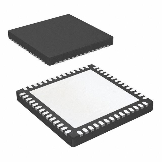
Figure 1: IR3536A Package Top View
1
June 21, 2013 | FINAL | V1.09
Figure 2: IR3538A Package Top View
�Digital Multi-Phase Buck Controller
IR3536A
IR3538A
ORDERING INFORMATION
IR353AM
Package
Packing
Qty
Part Number
QFN
TR=3000
TY=2600
IR3536AMTRPBF
IR3536AMTYPBF
Default
yy – Configuration File ID
QFN
TR=3000
TY=2600
IR3538AMTRPBF
IR3538AMTYPBF
Default
xx – Customer ID
QFN
TR=3000
IR3536AMxxyyTRP
P/PBF – Lead Free
TR – Tape & Reel / TY - Tray
Package Type (QFN)
Part –
6: IR3536A
8: IR3538A
Figure 3: IR3536A Package Top View, Enlarged
2
June 21, 2013 | FINAL | V1.09
QFN
TR=3000
Programming
1
1
IR3538AMxxyyTRP
Customer Configuration
Customer Configuration
Notes:
1.
Customer Specific Configuration File, where
xx = Customer ID and yy = Configuration File
(Codes assigned by IR Marketing).
Figure 4: IR3538A Package Top View, Enlarged
�IR3536A
IR3538A
Digital Multi-Phase Buck Controller
FUNCTIONAL BLOCK DIAGRAM
V18A
RCSP_L2
VCC
VID_2
RSCM_L2
1.8V
AFE_2
LDO
VSEN_L2
VRTN_L2
ITOT_2
RCSP
Vout1_Error
Voltage
ADC
PWM1
RSCM
Vout2_Error
AFE_1
PWM2
VSEN
VID_1
VRTN
PWM3
PWM4
ISEN1
Mode Control
IRTN1
.
.
.
ISENx
.
.
.
IP1
.
.
.
PWM5
Control
and
Monitoring
IPx
IRTNx
IR3536/
IR3538/
CHL8326
CHL8326 CHL8328
3
4
4
5
6
8
PWM Generator
Σ
Phase_
Period_1
Phase_
Period_2
ITOT_1
PWM7
x
y
z
PWM8
Iout
ISENy
IRTNy
.
.
.
ISENz
.
.
.
IRTNz
Vin
IPy
.
.
.
IPz
PWM6
ITOT_2
Only for
CHL8328
IR3538A
VAR_GATE
Vout
Temp
Σ
Current ADC
Fault Bus
System Clock
IP1
.
.
.
IP6
Only for
IR3538/ CHL8328
System Clock
IP7
.
.
.
IP8
ADC Clocks
MUX Clocks
1
Intel/MPoL mode
AMD mode
2
Phase_Period_1
TSEN2
Phase_Period_2
VID_1
TSEN
VID_2
VINSEN
Monitor ADC
V3_3
EN
SV_CLK1/SVC_VID[3]2
SV_DIO1/SVD_VID[2]2
SV_ALERT#1/VID[4]2
Reference,
Oscillator,
State Control,
Interfaces,
Registers and
NVM
Iout
Vin
Temp
Fault Bus
VR_HOT#1/
VRHOT_ICRIT#2
SMB_DIO
SMB_CLK
SMB_ALERT
VR_READY1/PWRGD2
VR_READY_L21/
PWROK2
GPO_A
Only for
GPO_B
CHL8328
IR3538A
PSI1/VID[5]2
SV_ADDR1/VID[1]2
PM_ADDR1/
PM_ADDR_VID[0]2
CFP1/VFIXEN_PSI2
RRES
Figure 5: IR3536A / IR3538A Functional Block Diagram
3
June 21, 2013 | FINAL | V1.09
�
很抱歉,暂时无法提供与“IR3538AMSM01TRP”相匹配的价格&库存,您可以联系我们找货
免费人工找货