PD - 97227A
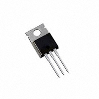
IRFB4228PbF
PDP SWITCH
Features
l Advanced Process Technology
l Key Parameters Optimized for PDP Sustain,
Energy Recovery and Pass Switch Applications
l Low E PULSE Rating to Reduce Power
Dissipation in PDP Sustain, Energy Recovery
and Pass Switch Applications
l Low QG for Fast Response
l High Repetitive Peak Current Capability for
Reliable Operation
l Short Fall & Rise Times for Fast Switching
l175°C Operating Junction Temperature for
Improved Ruggedness
l Repetitive Avalanche Capability for Robustness
and Reliability
Key Parameters
VDS min
VDS (Avalanche) typ.
RDS(ON) typ. @ 10V
IRP max @ TC= 100°C
TJ max
150
180
12
170
175
D
V
V
m:
A
°C
D
G
G
S
D
S
TO-220AB
G
D
S
Gate
Drain
Source
Description
This HEXFET® Power MOSFET is specifically designed for Sustain; Energy Recovery & Pass switch
applications in Plasma Display Panels. This MOSFET utilizes the latest processing techniques to achieve
low on-resistance per silicon area and low EPULSE rating. Additional features of this MOSFET are 175°C
operating junction temperature and high repetitive peak current capability. These features combine to
make this MOSFET a highly efficient, robust and reliable device for PDP driving applications.
Absolute Maximum Ratings
Max.
Parameter
VGS
ID @ TC = 25°C
Gate-to-Source Voltage
Continuous Drain Current, VGS @ 10V
ID @ TC = 100°C
IDM
IRP @ TC = 100°C
PD @TC = 25°C
PD @TC = 100°C
TJ
TSTG
Units
±30
V
A
Continuous Drain Current, VGS @ 10V
83
59
Pulsed Drain Current
Repetitive Peak Current
330
170
c
Power Dissipation
Power Dissipation
g
Linear Derating Factor
Operating Junction and
Storage Temperature Range
Soldering Temperature for 10 seconds
Mounting Torque, 6-32 or M3 Screw
330
170
W
2.2
-40 to + 175
W/°C
°C
x
300
x
10lb in (1.1N m)
N
Thermal Resistance
Parameter
RθJC
RθCS
RθJA
Junction-to-Case
f
Case-to-Sink, Flat, Greased Surface
Junction-to-Ambient
f
Typ.
–––
0.50
–––
Max.
0.45
–––
62
Units
°C/W
Notes through
are on page 8
www.irf.com
1
09/14/07
�IRFB4228PbF
Electrical Characteristics @ TJ = 25°C (unless otherwise specified)
Parameter
Min.
Typ. Max. Units
Drain-to-Source Breakdown Voltage
Breakdown Voltage Temp. Coefficient
150
–––
–––
150
–––
–––
VGS(th)
Static Drain-to-Source On-Resistance
Gate Threshold Voltage
–––
3.0
12
–––
15
5.0
∆VGS(th)/∆TJ
IDSS
Gate Threshold Voltage Coefficient
Drain-to-Source Leakage Current
–––
–––
-14
–––
–––
20
Gate-to-Source Forward Leakage
–––
–––
–––
–––
1.0
100
Gate-to-Source Reverse Leakage
Forward Transconductance
–––
170
–––
–––
-100
–––
Total Gate Charge
Gate-to-Drain Charge
–––
–––
71
21
107
–––
Turn-On Delay Time
Rise Time
–––
–––
18
59
–––
–––
Turn-Off Delay Time
Fall Time
–––
–––
24
33
–––
–––
Shoot Through Blocking Time
100
–––
–––
–––
58
–––
–––
110
–––
Input Capacitance
–––
4530
–––
Output Capacitance
Reverse Transfer Capacitance
–––
–––
550
100
–––
–––
Effective Output Capacitance
Internal Drain Inductance
–––
–––
480
4.5
–––
–––
BVDSS
∆ΒVDSS/∆TJ
RDS(on)
IGSS
gfs
Qg
Qgd
td(on)
tr
td(off)
tf
tst
EPULSE
Ciss
Coss
Crss
Coss eff.
LD
Energy per Pulse
VGS = 0V, ID = 250µA
V
mV/°C Reference to 25°C, ID = 1mA
mΩ VGS = 10V, ID = 33A
e
V
Internal Source Inductance
–––
7.5
VDS = VGS, ID = 250µA
mV/°C
µA VDS = 150V, VGS = 0V
mA VDS = 150V, VGS = 0V, TJ = 125°C
nA
VGS = 20V
VGS = -20V
S
VDS = 25V, ID = 50A
VDD = 75V, ID = 50A, VGS = 10V
nC
e
VDD = 75V, VGS = 10V
ns
ID = 50A
�e
RG = 2.5Ω
ns
µJ
pF
See Fig. 22
VDD = 120V, VGS = 15V, RG= 5.1Ω
L = 220nH, C= 0.3µF, VGS = 15V
VDS = 120V, RG= 5.1Ω, TJ = 25°C
L = 220nH, C= 0.3µF, VGS = 15V
VDS = 120V, RG= 5.1Ω, TJ = 100°C
VGS = 0V
VDS = 25V
ƒ = 1.0MHz
VGS = 0V, VDS = 0V to 120V
Between lead,
nH
LS
Conditions
–––
D
6mm (0.25in.)
from package
and center of die contact
G
S
Avalanche Characteristics
Typ.
Max.
Units
Single Pulse Avalanche Energy
–––
120
mJ
Repetitive Avalanche Energy
Repetitive Avalanche Voltage
–––
180
33
–––
mJ
–––
50
A
Parameter
EAS
EAR
VDS(Avalanche)
IAS
Avalanche Current
�d
d
c
�c
V
Diode Characteristics
Parameter
IS @ TC = 25°C Continuous Source Current
ISM
VSD
trr
Qrr
2
(Body Diode)
Pulsed Source Current
�c
Min.
Typ. Max. Units
–––
–––
83
–––
–––
330
Conditions
MOSFET symbol
A
(Body Diode)
Diode Forward Voltage
–––
–––
1.3
V
Reverse Recovery Time
Reverse Recovery Charge
–––
–––
76
230
110
350
ns
nC
showing the
integral reverse
p-n junction diode.
TJ = 25°C, IS = 50A, VGS = 0V
TJ = 25°C, IF = 50A, VDD = 50V
e
di/dt = 100A/µs
e
www.irf.com
�IRFB4228PbF
1000
1000
ID, Drain-to-Source Current (A)
100
BOTTOM
10
1
5.0V
0.1
TOP
ID, Drain-to-Source Current (A)
VGS
15V
10V
8.0V
7.0V
6.5V
6.0V
5.5V
5.0V
TOP
100
BOTTOM
5.0V
10
≤60µs PULSE WIDTH
≤60µs PULSE WIDTH
Tj = 25°C
0.01
Tj = 175°C
1
0.1
1
10
100
1000
0.1
V DS, Drain-to-Source Voltage (V)
10
100
1000
Fig 2. Typical Output Characteristics
3.5
RDS(on) , Drain-to-Source On Resistance
(Normalized)
1000
ID, Drain-to-Source Current (A)
1
V DS, Drain-to-Source Voltage (V)
Fig 1. Typical Output Characteristics
T J = 175°C
100
T J = 25°C
10
1
VDS = 25V
≤60µs PULSE WIDTH
ID = 50A
VGS = 10V
3.0
2.5
2.0
1.5
1.0
0.5
0.0
0.1
3
4
5
6
7
8
9
10
11
VGS, Gate-to-Source Voltage (V)
Fig 3. Typical Transfer Characteristics
-60 -40 -20 0 20 40 60 80 100120140160180
T J , Junction Temperature (°C)
Fig 4. Normalized On-Resistance vs. Temperature
120
120
L = 220nH
C = 0.3µF
100°C
25°C
100
90
L = 220nH
C = Variable
100°C
25°C
110
100
Energy per Pulse (µJ)
110
Energy per Pulse (µJ)
VGS
15V
10V
8.0V
7.0V
6.5V
6.0V
5.5V
5.0V
80
70
60
50
90
80
70
60
50
40
40
30
30
20
20
10
85
90
95
100 105 110 115 120 125
VDS, Drain-to-Source Voltage (V)
Fig 5. Typical EPULSE vs. Drain-to-Source Voltage
www.irf.com
60
65
70
75
80
85
90
95 100 105
ID, Peak Drain Current (A)
Fig 6. Typical EPULSE vs. Drain Current
3
�IRFB4228PbF
140
1000
L = 220nH
ISD, Reverse Drain Current (A)
Energy per Pulse (µJ)
120
100
C = 0.3µF
80
60
C = 0.2µF
40
C = 0.1µF
20
T J = 175°C
100
T J = 25°C
10
1
VGS = 0V
0
0.1
20
40
60
80
100
120
140
160
0.2
ID= 50A
C, Capacitance (pF)
VGS, Gate-to-Source Voltage (V)
C rss = C gd
C oss = C ds + C gd
Ciss
Coss
Crss
100
1.4
1.6
VDS= 30V
8.0
6.0
4.0
2.0
0.0
1
10
100
0
1000
10
20
30
40
50
60
70
80
QG, Total Gate Charge (nC)
VDS, Drain-to-Source Voltage (V)
Fig 9. Typical Capacitance vs.Drain-to-Source Voltage
90
Fig 10. Typical Gate Charge vs.Gate-to-Source Voltage
1000
OPERATION IN THIS AREA
LIMITED BY R DS(on)
ID, Drain-to-Source Current (A)
80
70
ID, Drain Current (A)
1.2
VDS= 120V
VDS= 75V
10.0
10
60
100µsec
100
50
40
30
20
10msec
0
1msec
10
Tc = 25°C
Tj = 175°C
Single Pulse
10
1
25
50
75
100
125
150
175
T J , Junction Temperature (°C)
Fig 11. Maximum Drain Current vs. Case Temperature
4
1.0
12.0
VGS = 0V,
f = 1 MHZ
C iss = C gs + C gd, C ds SHORTED
1000
0.8
Fig 8. Typical Source-Drain Diode Forward Voltage
Fig 7. Typical EPULSE vs.Temperature
10000
0.6
VSD, Source-to-Drain Voltage (V)
Temperature (°C)
100000
0.4
1
10
100
1000
VDS, Drain-to-Source Voltage (V)
Fig 12. Maximum Safe Operating Area
www.irf.com
�IRFB4228PbF
500
EAS , Single Pulse Avalanche Energy (mJ)
RDS(on) , Drain-to -Source On Resistance (mΩ)
60
ID = 50A
50
40
T J = 125°C
30
20
10
TJ = 25°C
0
400
300
200
100
0
4
6
8
10
12
14
16
18
VGS, Gate -to -Source Voltage (V)
Fig 13. On-Resistance vs. Gate Voltage
25
50
75
100
125
150
175
Starting T J , Junction Temperature (°C)
Fig 14. Maximum Avalanche Energy vs. Temperature
250
5.0
ton= 1µs
Duty cycle = 0.25
Half Sine Wave
Square Pulse
4.5
Repetitive Peak Current (A)
VGS(th) , Gate Threshold Voltage (V)
ID
TOP
13A
20A
BOTTOM 50A
4.0
3.5
ID = 250µA
3.0
2.5
2.0
200
150
100
50
1.5
0
1.0
-75 -50 -25
0
25
25 50 75 100 125 150 175
50
75
100
125
150
175
Case Temperature (°C)
T J , Temperature ( °C )
Fig 16. Typical Repetitive peak Current vs.
Case temperature
Fig 15. Threshold Voltage vs. Temperature
Thermal Response ( Z thJC )
1
D = 0.50
0.1
0.20
0.10
0.05
τJ
0.02
0.01
0.01
R1
R1
τJ
τ1
τ1
R2
R2
τ2
τ3
τ2
Ci= τi/Ri
Ci i/Ri
SINGLE PULSE
( THERMAL RESPONSE )
0.001
1E-006
1E-005
0.0001
R3
R3
τC
τ
τ3
Ri (°C/W) τi (sec)
0.0852 0.000052
0.1882
0.1769
0.000980
0.008365
Notes:
1. Duty Factor D = t1/t2
2. Peak Tj = P dm x Zthjc + Tc
0.001
0.01
0.1
1
t1 , Rectangular Pulse Duration (sec)
Fig 17. Maximum Effective Transient Thermal Impedance, Junction-to-Case
www.irf.com
5
�IRFB4228PbF
Driver Gate Drive
D.U.T
+
-
-
*
RG
•
•
•
•
***
D.U.T. ISD Waveform
Reverse
Recovery
Current
+
dv/dt controlled by RG
Driver same type as D.U.T.
I SD controlled by Duty Factor "D"
D.U.T. - Device Under Test
P.W.
Period
VGS=10V
Circuit Layout Considerations
• Low Stray Inductance
• Ground Plane
• Low Leakage Inductance
Current Transformer
-
D=
Period
P.W.
+
V DD
**
+
-
Body Diode Forward
Current
di/dt
D.U.T. VDS Waveform
Diode Recovery
dv/dt
Re-Applied
Voltage
Body Diode
VDD
Forward Drop
Inductor Curent
ISD
Ripple ≤ 5%
* Use P-Channel Driver for P-Channel Measurements
** Reverse Polarity for P-Channel
*** VGS = 5V for Logic Level Devices
Fig 18. Diode Reverse Recovery Test Circuit for HEXFET® Power MOSFETs
V(BR)DSS
15V
DRIVER
L
VDS
tp
D.U.T
RG
VGS
20V
+
V
- DD
IAS
A
0.01Ω
tp
I AS
Fig 19a. Unclamped Inductive Test Circuit
Fig 19b. Unclamped Inductive Waveforms
Current Regulator
Same Type as D.U.T.
Id
Vds
50KΩ
12V
Vgs
.2µF
.3µF
D.U.T.
+
V
- DS
VGS
Vgs(th)
3mA
IG
ID
Current Sampling Resistors
Fig 20a. Gate Charge Test Circuit
6
Qgs1 Qgs2
Qgd
Qgodr
Fig 20b. Gate Charge Waveform
www.irf.com
�IRFB4228PbF
A
RG
PULSE A
C
DRIVER
L
VCC
B
PULSE B
Ipulse
RG
DUT
tST
Fig 21b. tst Test Waveforms
Fig 21a. tst and EPULSE Test Circuit
Fig 21c. EPULSE Test Waveforms
V DS
VGS
RG
RD
VDS
90%
D.U.T.
+
-V DD
VGS
Pulse Width ≤ 1 µs
Duty Factor ≤ 0.1 %
Fig 22a. Switching Time Test Circuit
www.irf.com
10%
VGS
td(on)
tr
t d(off)
tf
Fig 22b. Switching Time Waveforms
7
�IRFB4228PbF
TO-220AB Package Outline (Dimensions are shown in millimeters (inches))
TO-220AB Part Marking Information
(;$03/(� 7+,6�,6�$1�,5)�����
/27�&2'(�����
$66(0%/('�21�::���������
,1�7+(�$66(0%/