StrongIRFET
IRFH7440PbF
HEXFET® Power MOSFET
Applications
l Brushed Motor drive applications
l BLDC Motor drive applications
l PWM Inverterized topologies
l Battery powered circuits
l Half-bridge and full-bridge topologies
l Electronic ballast applications
l Synchronous rectifier applications
l Resonant mode power supplies
l OR-ing and redundant power switches
l DC/DC and AC/DC converters
Benefits
l Improved Gate, Avalanche and Dynamic dV/dt
Ruggedness
l Fully Characterized Capacitance and Avalanche
SOA
l Enhanced body diode dV/dt and dI/dt Capability
l RoHS Compliant containing no Lead, no Bromide,
and no Halogen
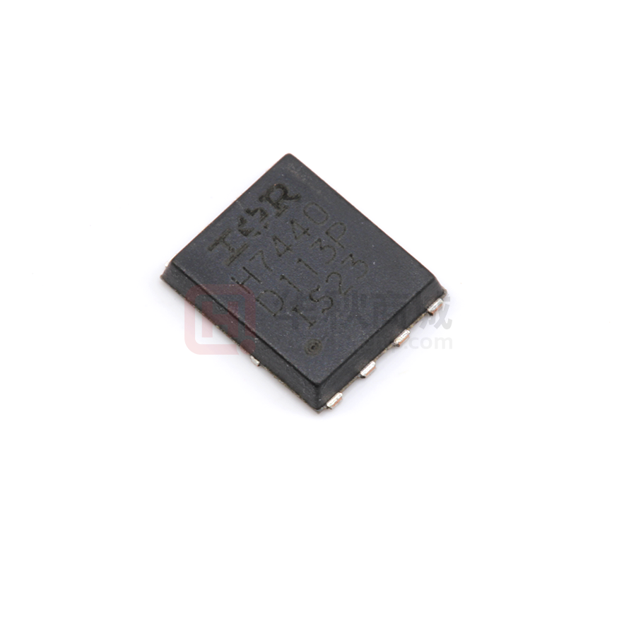
Package Type
IRFH7440PBF
PQFN 5mm x 6mm
PQFN 5mm x 6mm
Standard Pack
Form
Quantity
Tape and Reel
4000
Tape and Reel
400
6.0
ID (Package Limited)
85A
c
Orderable Part Number
Note
IRFH7440TRPBF
IRFH7440TR2PBF
EOL notice #259
200
ID = 50A
5.0
4.0
T J = 125°C
3.0
2.0
Limited By Package
150
100
50
TJ = 25°C
1.0
0
4
6
8
10
12
14
16
18
20
VGS, Gate -to -Source Voltage (V)
Fig 1. Typical On-Resistance vs. Gate Voltage
1
40V
1.8mΩ
2.4mΩ
159A
PQFN 5X6 mm
ID, Drain Current (A)
RDS(on), Drain-to -Source On Resistance (m Ω)
Base Part Number
VDSS
RDS(on) typ.
max.
ID (Silicon Limited)
www.irf.com © 2015 International Rectifier
25
50
75
100
125
150
T C , Case Temperature (°C)
Fig 2. Maximum Drain Current vs. Case Temperature
Submit Datasheet Feedback
July 7, 2015
�IRFH7440PbF
Absolute Maximum Ratings
Symbol
Parameter
Max.
Units
c
101c
159
ID @ TC = 25°C
Continuous Drain Current, VGS @ 10V (Silicon Limited)
ID @ TC = 100°C
Continuous Drain Current, VGS @ 10V (Silicon Limited)
ID @ TC = 25°C
Continuous Drain Current, VGS @ 10V (Package Limited)
IDM
Pulsed Drain Current
PD @TC = 25°C
Maximum Power Dissipation
104
W
Linear Derating Factor
0.83
W/°C
VGS
Gate-to-Source Voltage
± 20
V
dv/dt
Peak Diode Recovery
3.0
V/ns
TJ
Operating Junction and
d
624
f
-55 to + 150
Storage Temperature Range
TSTG
Avalanche Characteristics
Single Pulse Avalanche Energy
EAS (Thermally limited)
121
EAS (Thermally limited)
232
IAR
EAR
Thermal Resistance
Symbol
e
Single Pulse Avalanche Energy l
Avalanche Current�d
Repetitive Avalanche Energy d
RθJC (Top)
k
Junction-to-Case k
RθJA
Junction-to-Ambient
RθJC (Bottom)
RθJA (
很抱歉,暂时无法提供与“IRFH7440TRPBF”相匹配的价格&库存,您可以联系我们找货
免费人工找货- 国内价格
- 1+2.77560
- 10+2.20320
- 30+1.95480
- 100+1.64160
- 500+1.50120
- 1000+1.41480
- 国内价格 香港价格
- 4000+5.797674000+0.75002
- 8000+5.429268000+0.70236
- 12000+5.2416512000+0.67809
- 国内价格
- 1+2.54430
- 10+2.01960
- 800+1.29690