IRFHS9351PbF
HEXFET® Power MOSFET
VDS
VGS max
-30
±20
V
V
RDS(on) max
170
mΩ
(@VGS = -10V)
ID
-3.4
(@TC = 25°C)
d
A
T OP VIEW
S1 1
6 D1
S2
D1
G1 2
FET 1
D1
D1
D2
5 G2
D2
D2 3
G2
4 S2
D2
FET 2
G1
S1
2mm x 2mm Dual PQFN
Applications
l
l
Charge and Discharge Switch for Battery Application
System/load switch
Features and Benefits
Features
Low RDSon (≤ 170mΩ)
Benefits
Lower Conduction Losses
Low Thermal Resistance to PCB (≤ 19°C/W)
Enable better thermal dissipation
Low Profile (≤ 1.0 mm)
results in
Increased Power Density
Compatible with Existing Surface Mount Techniques
Easier Manufacturing
RoHS Compliant Containing no Lead, no Bromide and no Halogen
MSL1, Industrial Qualification
Increased Reliability
Orderable part number
Package Type
IRFHS9351TRPBF
IRFHS9351TR2PBF
Environmentally Friendlier
Standard Pack
Form
Quantity
PQFN 2mm x 2mm
Tape and Reel
4000
PQFN 2mm x 2mm
Tape and Reel
400
Note
EOL notice # 259
Absolute Maximum Ratings
VDS
VGS
ID @ TA = 25°C
ID @ TA = 70°C
ID @ TC = 25°C
ID @ TC = 70°C
Parameter
Drain-to-Source Voltage
Gate-to-Source Voltage
Continuous Drain Current, VGS @ -10V
Continuous Drain Current, VGS @ -10V
Continuous Drain Current, VGS @ -10V
Continuous Drain Current, VGS @ -10V
ID @ TC = 25°C
IDM
PD @TA = 25°C
PD @ TA = 70°C
Continuous Drain Current, VGS @ 10V (Package Limited)
Pulsed Drain Current
Power Dissipation
Power Dissipation
TJ
TSTG
Linear Derating Factor
Operating Junction and
Storage Temperature Range
f
f
Max.
-30
± 20
-2.3
-1.5
-5.1
-4.1
-3.4
-20
1.4
0.9
Units
0.01
-55 to + 150
W/°C
d
d
d
c
V
A
W
°C
Notes through are on page 2
1
www.irf.com © 2014 International Rectifier
Submit Datasheet Feedback
May 21, 2014
�IRFHS9351PbF
Static @ TJ = 25°C (unless otherwise specified)
Parameter
BVDSS
VDSS/ TJ
RDS(on)
Min.
Typ.
Max.
Units
Drain-to-Source Breakdown Voltage
-30
–––
–––
V
Breakdown Voltage Temp. Coefficient
–––
0.02
–––
V/°C
–––
135
170
–––
235
290
Static Drain-to-Source On-Resistance
V GS(th)
VGS(th)
IDSS
IGSS
m
Gate Threshold Voltage
-1.3
-1.8
-2.4
V
Gate Threshold Voltage Coefficient
–––
-4.6
–––
mV/°C
Drain-to-Source Leakage Current
–––
–––
-1.0
–––
–––
-150
μA
Gate-to-Source Forward Leakage
–––
–––
-100
Gate-to-Source Reverse Leakage
–––
–––
100
gfs
Forward Transconductance
2.4
–––
–––
S
–––
1.9
–––
nC
–––
3.7
–––
–––
0.6
–––
–––
1.1
–––
h
h
Qg
Total Gate Charge
Qg
Total Gate Charge
Qgs
Gate-to-Source Charge
h
Gate-to-Drain Charge h
Gate R esistance h
Qgd
RG
nA
Conditions
V GS = 0V, I D = -250μA
Reference to 25°C, ID = -1mA
V GS = -10V, I D = -3.1A
e
e
V GS = -4.5V, ID = -2.5A
V DS = V GS, ID = -10μA
V DS = -24V, VGS = 0V
V DS = -24V, VGS = 0V, T J = 125°C
V GS = -20V
V GS = 20V
V DS = -10V, ID = -3.1A
V DS = -15V,VGS = -4.5V,ID = - 3.1A
V GS = -10V
nC
V DS = -15V
I D = -3.1A
–––
17
–––
Turn-On Delay Time
–––
8.3
–––
V DD = -15V, V GS = -4.5V
tr
Rise Time
–––
30
–––
I D = -3.1A
td(off )
Turn-Off Delay Time
–––
6.3
–––
tf
Fall Time
–––
7.9
–––
Ciss
Input Capacitance
–––
160
–––
td(on)
Coss
Output Capacitance
–––
39
–––
Crss
Reverse Transfer C apacitance
–––
26
–––
Min.
Typ.
Max.
ns
e
RG = 1.8
See Figs. 19a & 19b
V GS = 0V
pF
V DS = -25V
ƒ = 1.0KHz
Diode Characteristics
Parameter
IS
Continuous Source Current
(Body Diode)
ISM
–––
-5.1
–––
–––
-20
�c
-1.2
V SD
Diode Forward Voltage
–––
–––
trr
Reverse Recovery Time
–––
20
Qrr
Reverse Recovery Charge
–––
42
Conditions
MOSFET symbol
A
Pulsed Source Current
(Body Diode)
–––
Units
integral reverse
Parameter
JC
(Bottom)
R
JC
(Top)
g
Junction-to-Case g
Junction-to-Case
f
R
JA
Junction-to-Ambient
R
JA
Junction-to-Ambient (t
很抱歉,暂时无法提供与“IRFHS9351TRPBF”相匹配的价格&库存,您可以联系我们找货
免费人工找货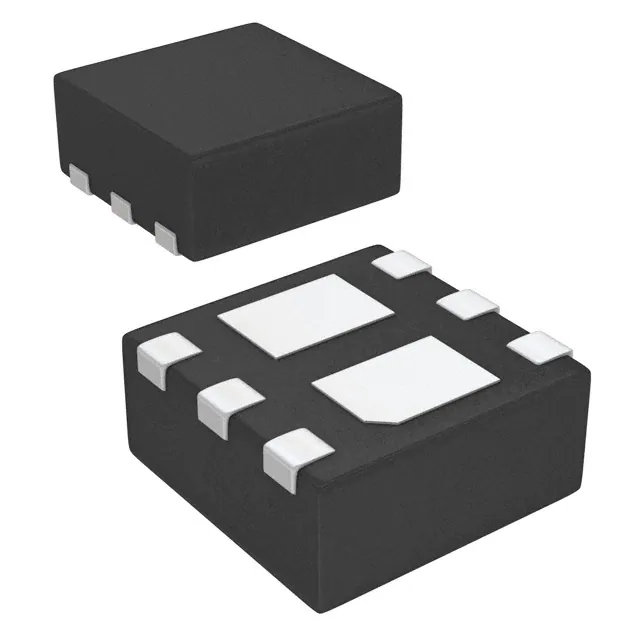


 工商网监
湘ICP备2023018690号
工商网监
湘ICP备2023018690号
