Final Datasheet V1.0
TS
Rev.
Page
of
TPM Sensor SP30T
SensoNor
Final Datasheet V1.0
Tire Pressure Monitoring Sensor SP30T
Revisions dates:
00
2007-06-11
1
2007-12-20
2
2008-05-29
Document history: See end of document
Date
Sign
Rev
Reference
Date
Dok
Prepared
070611
ML
0
Archive
11843
070813
HKW
Checked
070613
NPH
1
EM
11866
080616
HKW
Approved
070716
RH
2
EM
12044
080616
Stamp
1378
2
1
13
�Final Datasheet V1.0
SensoNor
TPM Sensor SP30T
TS
Rev.
Page
of
1378
2
2
13
Table of Contents
1
2
PRODUCT DESCRIPTION.......................................................................................................................................4
1.1
Overview...........................................................................................................................................................4
1.2
Features ...........................................................................................................................................................4
1.3
Ordering Information ........................................................................................................................................4
PRODUCT CHARACTERISTICS.............................................................................................................................5
2.1
Measurement Performance..............................................................................................................................5
2.1.1 Pressure Measurement................................................................................................................................5
2.1.2 Acceleration Measurement ..........................................................................................................................6
2.1.3 Temperature Measurement .........................................................................................................................6
2.1.4 Supply Voltage Measurement......................................................................................................................6
2.2
Current Consumption .......................................................................................................................................7
2.3
Tmax.................................................................................................................................................................7
2.4
Vmin .................................................................................................................................................................7
2.5
Clock Sources ..................................................................................................................................................8
2.5.1 System Clock (MCLK)..................................................................................................................................8
2.5.2 Low Power (LP) Oscillator ...........................................................................................................................8
2.5.3 External Clock ..............................................................................................................................................8
2.6
LF Input ............................................................................................................................................................8
2.7
Power-on Reset................................................................................................................................................9
2.8
Digital I/O..........................................................................................................................................................9
3
OPERATING RANGE...............................................................................................................................................9
4
ABSOLUTE MAXIMUM RATINGS ........................................................................................................................10
5
PHYSICAL DIMENSIONS ......................................................................................................................................11
6
PIN CONFIGURATION...........................................................................................................................................12
7
DOCUMENT HISTORY ..........................................................................................................................................13
�Final Datasheet V1.0
SensoNor
TPM Sensor SP30T
TS
Rev.
Page
of
1378
2
3
13
Edition 2008-05-29
Published by Infineon Technologies AG,
Am Campeon 1-12
85579 Neubiberg, Germany
© Infineon Technologies AG 2006-03-20.
All Rights Reserved.
Attention please!
The information herein is given to describe certain components and shall not be considered as a guarantee of
characteristics.
Terms of delivery and rights to technical change reserved.
We hereby disclaim any and all warranties, including but not limited to warranties of non-infringement, regarding
circuits, descriptions and charts stated herein.
Information
For further information on technology, delivery terms and conditions and prices please contact your nearest
Infineon Technologies Office in Germany or the Infineon Technologies Companies and our Infineon Technologies
Representatives worldwide (www.infineon.com).
Warnings
Due to technical requirements components may contain dangerous substances. For information on the types in
question please contact your nearest Infineon Technologies Office.
Infineon Technologies Components may only be used in life-support devices or systems with the express written
approval of Infineon Technologies, if a failure of such components can reasonably be expected to cause the failure
of that life-support device or system, or to affect the safety or effectiveness of that device or system. Life support
devices or systems are intended to be implanted in the human body, or to support and/or maintain and sustain
and/or protect human life. If they fail, it is reasonable to assume that the health of the user or other persons may
be endangered.
�Final Datasheet V1.0
TPM Sensor SP30T
SensoNor
TS
Rev.
Page
of
1378
2
4
13
1 Product Description
1.1
Overview
The SP30T Tire Pressure Monitoring (TPM) Sensor represents Infineon’s high pressure range TPM sensor for SUV
and Truck application. The SP30T combines a high pressure range with a high level of integration by including a
microcontroller and LF-input stage to meet market demands for flexible, customer specific solutions and overall
system cost reduction.
The sensor design is based upon Infineon’s proprietary and patented solutions for high reliability measurements in
harsh automotive environments, with a predictable and stable quality in high volume applications.
The SP30T measures pressures up to 1600kPa, temperature, supply voltage and acceleration (optional), and by
integrating these functions with an ASIC in one package, Infineon has developed the ideal product for high pressure
TPM applications.
1.2
Features
•
•
•
1.3
Integrated Sensors
o High pressure range
o Acceleration
o Temperature
o Voltage
Integrated Peripherals
o Microcontroller
o On board EEPROM
o GPIOs
o ADC for signal conditioning
o 2x LF Receiver for triggering
Measurement Ranges
o Pressure Sensor 100 to 1600 kPa
o Temperature Sensor -40 to +125°C
o Supply Voltage Sensor 2.1 to 3.6 V
o Acceleration Sensor -12 to 115 g
Ordering Information
Product Name
SP30T-00E00-06B
Product Type
Tire Pressure Monitoring Sensor
Ordering Code
SP000411794
Package
P-DSOSP-14-6
�Final Datasheet V1.0
TPM Sensor SP30T
SensoNor
TS
Rev.
Page
of
1378
2
5
13
2 Product Characteristics
The max and min numbers are to be understood as + and – 5σ values (Cpk = 1.67) unless otherwise specified.
2.1
Measurement Performance
2.1.1 Pressure Measurement
The presented performance reflects the use of 11-bit measurement of pressure signal and 10-bit measurement of
temperature.
Table 1 Pressure measurement specifications
PARAMETER
Input pressure range*
Measurement error
Min
100
-25
-30
-45
-50
SPECIFICATION
Typ Max
Unit
1600
kPa
25
kPa
30
kPa
45
kPa
50
kPa
AMBIENT CONDITIONS
Temp [°C]
VDD [V] Pressure [kPa]
-40 to 125
2.1 to 3.6
0 to 50
2.1 to 3.6
100 to1000
-40 to 125
2.1 to 3.6
0 to 50
2.1 to 3.6
1000 to1600
-40 to 125
2.1 to 3.6
Table 2 Pressures 100, 375, 657, 1000, 1300, 1600 kPa verified in qualification
LSL @ -40 --> 125°C
USL @ -40 --> 125°C
SP30T Pressure Specification
LSL @ 0 --> 50°C
USL @ 55
0 --> 50°C
45
Measurement error [kPa]
35
25
15
5
-5100
200 300
400 500
600 700
800 900 1000 1100 1200 1300 1400 1500 1600
-15
-25
-35
-45
-55
Input Pressure [kPa]
Figure 1: Pressure measurement error
COMMENTS
Linear behavior
between 1000
kPa and 1600
kPa according to
Figure 1
�Final Datasheet V1.0
TPM Sensor SP30T
SensoNor
TS
Rev.
Page
of
1378
2
6
13
2.1.2 Acceleration Measurement
The presented performance reflects the use of 12-bit measurement of acceleration signal and 10-bit measurement for
temperature.
Table 2 Acceleration measurement specifications
SPECIFICATION
PARAMETER
Min
Typ
Max
Unit
Input acceleration range
-12
115
g
Sensitivity error
-18.75
18.75
%
-24
24
Offset error@9g
-6
6
g
-8.5
8.5
-12
12
AMBIENT CONDITIONS
Temp [°C]
VDD [V]
-40 to 125
2.1 to 3.6
-40 to 90
2.1 to 3.6
90 to 125
-20 to 70
2.1 to 3.6
-40 to 90
90 to 125
COMMENTS
2.1.3 Temperature Measurement
The presented performance reflects the use of 10-bit measurement of temperature.
Table 3 Temperature measurement specifications
PARAMETER
Measurement error
Min
-3
-5
-3
SPECIFICATION
Typ
Max
3
5
7
Unit
°C
°C
°C
AMBIENT CONDITIONS
Temp [°C]
VDD [V]
-20 to 70
2.1 to 3.6
-40 to 90
2.1 to 3.6
90 to 125
2.1 to 3.6
COMMENTS
2.1.4 Supply Voltage Measurement
The presented performance reflects the use of 9-bit measurement of supply voltage.
Table 4 Supply voltage measurement specifications
PARAMETER
Measurement error
Min
-100
SPECIFICATION
Typ
Max
Unit
+100
mV
AMBIENT CONDITIONS
TEMP [°C]
VDD [V]
-40 to 125
VTHR to 3.6
COMMENTS
�Final Datasheet V1.0
TPM Sensor SP30T
SensoNor
2.2
TS
Rev.
Page
of
1378
2
7
13
Current Consumption
Table 5 Current consumption
PARAMETER
Min
Power down current
Power down current
IDLE current
IDLE current
RUN current
RUN current
Pressure measurement
Acceleration measurement
SPECIFICATION
Typ Max
Unit
0.4
0.6
µA
13
20
µA
30
50
µA
50
75
µA
0.53
0.8
mA
0.65
1.0
mA
4
12
µAs
AMBIENT CONDITIONS
Temp [°C]
VDD [V]
25
3.0
125
3.0
25
3.0
125
3.0
25
3.0
125
3.0
-40 to 125
2.1 to 3.6
6
16
µAs
-40 to 125
2.1 to 3.6
Temperature measurement
Supply voltage measurement
Peak current
0.9
0.3
1.6
2.5
2.5
2.5
µAs
µAs
mA
-40 to 125
-40 to 125
25
2.1 to 3.6
2.1 to 3.6
3.0
1 channel LF current
1 channel LF current
2 channel LF current
2.6
3.0
4.5
4.6
6.7
5.5
µA
µA
µA
25
125
25
3.0
3.0
3.0
2 channel LF current
6.5
11
µA
125
3.0
Thermal shutdown current
Thermal shutdown current
18
30
25
50
µA
µA
125
150
3.0
3.0
2.3
COMMENTS
11 bit A/D conversion,
excl. temperature meas
12 bit A/D conversion,
excl. temperature meas
10 bit A/D conversion
9 bit A/D conversion
Pressure measurement
and 1 LF channel on,
duration is 1280µs for
11 bit measurement for
the peak current only.
nd
2 LF channel is
optional
nd
2 LF channel is
optional
Tmax
ϑSHTD represents the temperature at which the Thermal Shut-down function can be enabled and ϑREL represents the
temperature at which the Master Reset state is released. The ϑSHTD is always higher than ϑREL.
Table 6 Trigger temperatures for thermal shutdown
PARAMETER
ϑSHTD
ϑREL
Min
102
100
SPECIFICATION
Typ
Max
Unit
123
°C
121
°C
AMBIENT CONDITIONS
COMMENTS
TEMP [°C]
VDD [V]
-40 to 175
2.1 to 3.6 Thermal shutdown enable
-40 to 175
2.1 to 3.6 Master Reset release
2.4
Vmin
The voltage at which the Vmin-circuit will return a low battery voltage status is specified in Table :
Table 7 Vmin specifications
PARAMETER
Vmin
Min
2.0
SPECIFICATION
Typ
Max
Unit
2.1
2.2
V
AMBIENT CONDITIONS
TEMP [°C]
VDD [V]
-40 to 125
VTHR to 3.6
COMMENTS
�Final Datasheet V1.0
TPM Sensor SP30T
SensoNor
2.5
TS
Rev.
Page
of
1378
2
8
13
Clock Sources
2.5.1
System Clock (MCLK)
Table 8 System clock (MCLK) specifications
PARAMETER
MCLK frequency
2.5.2
Min
1.8
SPECIFICATION
Typ
Max
Unit
2.0
2.2
MHz
AMBIENT CONDITIONS
TEMP [°C]
VDD [V]
-40 to 125
2.1 3.6
COMMENTS
Low Power (LP) Oscillator
Table 9 LP oscillator specifications
PARAMETER
Tit
del2t
LP oscillator accuracy
2.5.3
SPECIFICATION
Min
Typ
Max
Unit
0.5, 1.0, 2.0 or 4.0
s
25, 50, 75 or 100
ms
-20
20
%
AMBIENT CONDITIONS
TEMP [°C]
VDD [V]
-40 to 125
2.1 to 3.6
-40 to 125
2.1 to 3.6
-40 to 125
2.1 to 3.6
COMMENTS
Interval timer main tick
Delay to extra tick
External Clock
Table 10 External clock specifications
PARAMETER
Min
External clock
2.6
SPECIFICATION
Typ
Max
Unit
3.5
MHz
AMBIENT CONDITIONS
TEMP [°C]
VDD [V]
-40 to 125
2.1 to 3.6
COMMENTS
LF Input
Table 11 LF telegram
PARAMETER
Modulation
Carrier frequency
Preamble period
Data rate
Settling time
Detection threshold
Input capacitance
Input resistance
Other
SPECIFICATION
Typ
Max
ASK
121.25
125
128.75
4
3.84
3.9
3.96
2
AMBIENT CONDITIONS
COMMENTS
TEMP [°C]
VDD [V]
-40 to 125
2.1 to 3.6
kHz
-40 to 125
2.1 to 3.6
ms
-40 to 125
2.1 to 3.6
kHz
-40 to 125
2.1 to 3.6
ms
-40 to 125
2.1 to 3.6 Time from LF interface
is turned on by RISC to
the LF interface is
active
5
mVp-p
-40 to 125
2.1 to 3.6
10
12
pF
-40 to 125
2.1 to 3.6
500
-40 to 125
2.1 to 3.6
kΩ
The input signals from the enabled LF channels are rectified and real time summed
Min
Unit
�Final Datasheet V1.0
TPM Sensor SP30T
SensoNor
TS
Rev.
Page
of
Table 12 LF Carrier Detection
PARAMETER
Carrier frequency
Maximum sensitivity not to
detect, 2 amplifiers
enabled
Minimum sensitivity to
detect, 2 amplifiers
enabled
Maximum sensitivity not to
detect, 3 amplifiers
enabled
Minimum sensitivity to
detect, 3 amplifiers
enabled
2.7
Min
121.25
4
3.5
3.5
2.9
10
12.2
12.2
SPECIFICATION
Typ
Max
125
128.75
0.8
0.25
0.25
2.5
Unit
kHz
mVp-p
mVp-p
mVp-p
mVp-p
mVp-p
mVp-p
mVp-p
mVp-p
mVp-p
mVp-p
mVp-p
AMBIENT CONDITIONS
COMMENTS
TEMP [°C]
VDD [V]
-40 to 125
2.1 to 3.6
0 to 90
2.1 to 3.6
90 to 125
2.1 to 3.6
-40 to 0
2.1 to 3.0
-40 to 0
3.0 to 3.6
0 to 90
2.1 to 3.6
90 to 125
2.1 to 3.6
-40 to 0
2.1 to 3.6
-40
3.6
-40
2.1 to 3.0
0 to 125
2.1 to 3.6
-40 to 125
2.1 to 3.6
Power-on Reset
Table 13 Power-on reset level
PARAMETER
Power-on reset level, VTHR
2.8
Min
1.8
SPECIFICATION
Typ
Max
Unit
1.85
1.9
V
COMMENTS
Digital I/O
Table 14 Digital I/O specifications
PARAMETER
Digital output high
Digital output low
Digital input high
Digital input low
Input current
SPECIFICATION
COMMENTS
Min
Typ
Max
Unit
VDD-0.3
V At 1 mA load current
0.3
V At 1 mA load current
V
0.8⋅VDD
V
0.2⋅VDD
±1
µA
3 Operating Range
Table 15 Operating range
PARAMETER
Supply voltage
Ambient temperature
Min
VTHR
-40
SPECIFICATION
Typ
Max
Unit
3.6
V
125
°C
COMMENTS
Unless otherwise specified
1378
2
9
13
�Final Datasheet V1.0
TPM Sensor SP30T
SensoNor
TS
Rev.
Page
of
1378
2
10
13
4 Absolute Maximum Ratings
Table 16 Absolute maximum ratings
PARAMETER
Ambient temperature, operating
Ambient temperature, storage
1
Transient temperature
Supply Voltage
Input voltage
Input current, any pin (DC)
Input current, any pin (transient)
Input current, LF pins
Maximum input pressure
Static acceleration
Mechanical shock
ESD HBM
ESD CDM
Min
-40
-40
-0.3
-0.3
-10
-100
-1
50
2
750
SPECIFICATION
Typ
Max
150
150
175
4.0
Vdd+0.3
10
100
1
2000
2500
3000
4000
Unit
°C
°C
°C
V
V
mA
mA
mA
kPa
kPa
g
g
kV
V
500
Latch Up
1
100
mA
COMMENTS
Max 24 h accumulated over life time
Max 1000 h
Max 3 min
Max 2 s, 5 times over lifetime
Half sine, 0.3ms
Human body model JESD22-A114
Charge Device Model ESD-STM5.3.1,
Corner pins
Charge Device Model ESD-STM5.3.1,
All other pins
AEC-Q100
Will withstand standard SnPb Eutectic reflow soldering process (JEDEC J-STD-020, J-STD-A113)
Attention: Stresses above the max. values listed here may cause permanent damage to the device.
Exposure to absolute maximum rating conditions for extended periods may affect device
reliability. Maximum ratings are absolute ratings; exceeding only one of these values may
cause irreversible damage to the device.
�Final Datasheet V1.0
SensoNor
TPM Sensor SP30T
TS
Rev.
Page
of
1378
2
11
13
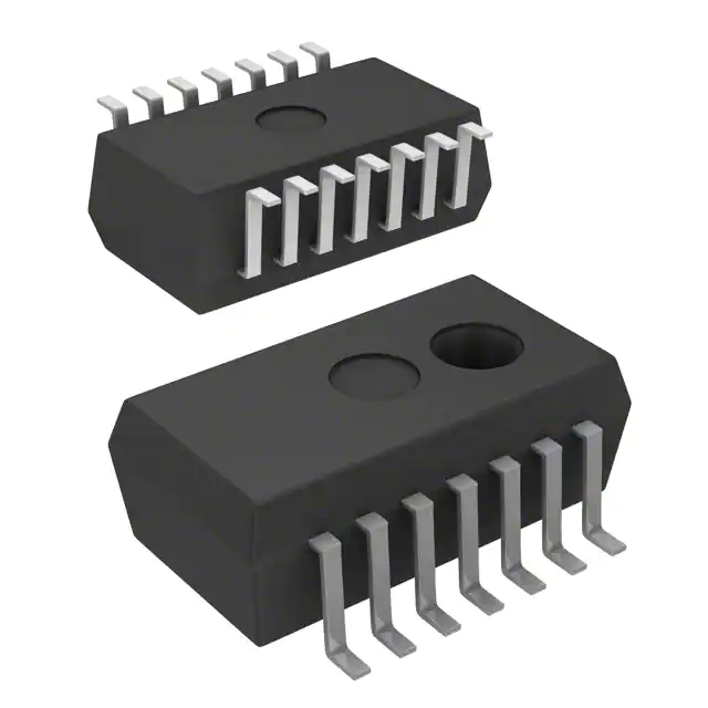
5 Physical dimensions
Figure 2: Physical Dimensions – Drawing P-DSOSP-14-6 1) Dimension does not include mold flash, protrusions or
gate burrs. Mold flash, protrusions and gate burrs do not exceed 0.15mm (0.006 inch) per side. 2) Dimension does
not include inter-lead flash or protrusions. Inter-lead flash and protrusions do not exceed
0.25mm (0.010 inch) per side.
�Final Datasheet V1.0
TPM Sensor SP30T
SensoNor
TS
Rev.
Page
of
6 Pin Configuration
Figure 3: Pin Configuration. Top view, not to scale
Table 17 Pin Description
PIN
NAME
FUNCTION
1
2
3
4
5
6
7
8
9
10
11
12
13
14
IN4
P10
P11
MSDA
MSCL
VDD
VSS
VSS
P17
P15
P14
IN1
IN2
IN3
LF receiver channel 2, negative input
General purpose I/O with external wakeup, internal pull-up/pull-down
General purpose I/O with external wakeup, internal pull-up/pull-down
Monitor Serial Data I/O, internal pull-up
Monitor Serial Clock input
Supply pad VDD (battery, positive terminal)
Common ground (battery, negative terminal)
Common ground (battery, negative terminal)
General purpose I/O (or digital modulator output)
General purpose I/O or external clock
General purpose I/O (or digital modulator output)
LF receiver channel 1, positive input
LF receiver channel 1, negative input
LF receiver channel 2, positive input
1378
2
12
13
�Final Datasheet V1.0
TPM Sensor SP30T
SensoNor
TS
Rev.
Page
of
1378
2
13
13
7 Document history
Rev
00
1
1
1
1
2
2
2
2
2
2
Paragraphs
1
2.1.1
2.1.1
5
1
5
5
6
2
Description
First issue of TS1378
Disclaimer included
Pressure range extended from max 1500kPa to max 1600kPa. Measurement error
adjusted accordingly.
Footnote included displaying the Pressure values verified in qualification
Physical Drawing updated
Added section “Product Description “
Physical Drawing updated
Added wording to Figure title of figure 2
Added section “Pin Configuration”
Removed “Confidential” marking
Updated fig. 1
�


 工商网监
湘ICP备2023018690号
工商网监
湘ICP备2023018690号
