OPTIREG™ Linear TLE4271-2
5-V low drop fixed voltage regulator
Features
•
Output voltage tolerance ≤ ±2%
•
Low-drop voltage
•
Integrated overtemperature protection
•
Reverse polarity protection
•
Input voltage up to 42 V
•
Overvoltage protection up to 65 V (≤ 400 ms)
•
Short-circuit proof
•
Suitable for use in automotive electronics
•
Wide temperature range
•
Adjustable reset and watchdog time
•
Green Product (RoHS compliant)
Potential applications
General automotive applications.
Product validation
Qualified for automotive applications. Product validation according to AEC-Q100/101.
Description
The OPTIREG™ Linear TLE4271-2 is functional and electrical identical to TLE4271.
The device is a 5-V low drop fixed voltage regulator. The maximum input voltage is 42 V (65 V, ≤ 400 ms). Up to
an input voltage of 26 V and for an output current up to 550 mA it regulates the output voltage within a 2%
accuracy. The short circuit protection limits the output current of more than 650 mA. The IC can be switched
off via the inhibit input. An integrated watchdog monitors the connected controller. The device incorporates
overvoltage protection and temperature protection that disables the circuit at overtemperature.
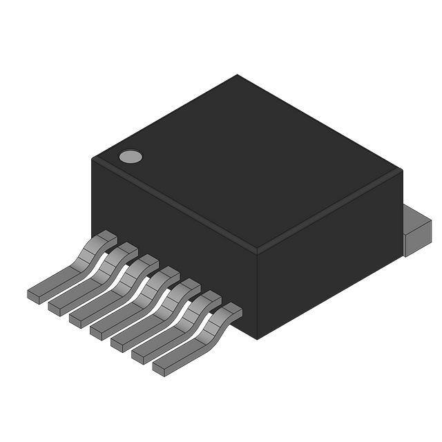
Type
Package
Marking
TLE4271-2G
PG-TO263-7
4271-2G
Datasheet
www.infineon.com/OPTIREG-Linear
1
Rev. 2.8
2019-07-30
�OPTIREG™ Linear TLE4271-2
5-V low drop fixed voltage regulator
Table of contents
Features . . . . . . . . . . . . . . . . . . . . . . . . . . . . . . . . . . . . . . . . . . . . . . . . . . . . . . . . . . . . . . . . . . . . . . . . 1
Potential applications . . . . . . . . . . . . . . . . . . . . . . . . . . . . . . . . . . . . . . . . . . . . . . . . . . . . . . . . . . . . . 1
Product validation . . . . . . . . . . . . . . . . . . . . . . . . . . . . . . . . . . . . . . . . . . . . . . . . . . . . . . . . . . . . . . . . 1
Description . . . . . . . . . . . . . . . . . . . . . . . . . . . . . . . . . . . . . . . . . . . . . . . . . . . . . . . . . . . . . . . . . . . . . . 1
Table of contents . . . . . . . . . . . . . . . . . . . . . . . . . . . . . . . . . . . . . . . . . . . . . . . . . . . . . . . . . . . . . . . . . 2
1
Block diagram . . . . . . . . . . . . . . . . . . . . . . . . . . . . . . . . . . . . . . . . . . . . . . . . . . . . . . . . . . . . . . . . . . . 3
2
Pin configuration . . . . . . . . . . . . . . . . . . . . . . . . . . . . . . . . . . . . . . . . . . . . . . . . . . . . . . . . . . . . . . . . . 4
3
3.1
3.2
3.3
General product characteristics . . . . . . . . . . . . . . . . . . . . . . . . . . . . . . . . . . . . . . . . . . . . . . . . . . . .
Absolute maximum ratings . . . . . . . . . . . . . . . . . . . . . . . . . . . . . . . . . . . . . . . . . . . . . . . . . . . . . . . . . . . . . . . .
Operating range . . . . . . . . . . . . . . . . . . . . . . . . . . . . . . . . . . . . . . . . . . . . . . . . . . . . . . . . . . . . . . . . . . . . . . . . . .
Characteristics . . . . . . . . . . . . . . . . . . . . . . . . . . . . . . . . . . . . . . . . . . . . . . . . . . . . . . . . . . . . . . . . . . . . . . . . . . .
4
Circuit description . . . . . . . . . . . . . . . . . . . . . . . . . . . . . . . . . . . . . . . . . . . . . . . . . . . . . . . . . . . . . . . . 9
5
Typical performance characteristics . . . . . . . . . . . . . . . . . . . . . . . . . . . . . . . . . . . . . . . . . . . . . . . 13
6
Package information . . . . . . . . . . . . . . . . . . . . . . . . . . . . . . . . . . . . . . . . . . . . . . . . . . . . . . . . . . . . . 18
7
Revision history . . . . . . . . . . . . . . . . . . . . . . . . . . . . . . . . . . . . . . . . . . . . . . . . . . . . . . . . . . . . . . . . . 19
Datasheet
2
5
5
6
7
Rev. 2.8
2019-07-30
�OPTIREG™ Linear TLE4271-2
5-V low drop fixed voltage regulator
Block diagram
1
Block diagram
Saturation
Control and
Protection
Circuit
Temperature
Sensor
Ι
7
1
Control
Amplifier
Adjustment
Bandgap
Reference
3
Buffer
+
-
Reset
Generator
Watchdog
2
INH
Figure 1
Datasheet
4
GND
5
6
Q
RO
D
WI
AEB01940
Block diagram
3
Rev. 2.8
2019-07-30
�OPTIREG™ Linear TLE4271-2
5-V low drop fixed voltage regulator
Pin configuration
2
Pin configuration
1
7
I
Figure 2
Pin configuration (top view)
Table 1
Pin definitions and functions
RO
Q
D
INH GND WI
Pin
Symbol
Function
1
I
Input
Block to ground directly on the IC with ceramic capacitor.
2
INH
Inhibit
3
RO
Reset output
The open collector output is connected to the 5 V output via an integrated resistor of
30 kΩ.
4
GND
Ground
5
D
Reset delay
Connect a capacitor to ground for delay time adjustment.
6
WI
Watchdog input
7
Q
5-V output
Block to ground with 22 µF capacitor, ESR < 3 Ω.
Datasheet
4
Rev. 2.8
2019-07-30
�OPTIREG™ Linear TLE4271-2
5-V low drop fixed voltage regulator
General product characteristics
3
General product characteristics
3.1
Absolute maximum ratings
Table 2
Absolute maximum ratings
Tj = -40°C to 150°C
Parameter
Symbol
Values
Min.
Typ.
Max.
Unit
Note or
Test Condition
Input
Voltage
VI
-42
–
42
V
–
Voltage
VI
–
–
65
V
t ≤ 400 ms
Current
II
–
–
–
mA
Internally limited
Voltage
VINH
-42
–
42
V
–
Voltage
VINH
–
–
65
V
t ≤ 400 ms
Current
IINH
–
–
–
mA
Internally limited
Voltage
VRO
-0.3
–
42
V
–
Current
IRO
–
–
–
mA
Internally limited
Voltage
VD
-0.3
–
7
V
–
Current
ID
-5
–
5
mA
–
Voltage
VW
-0.3
–
7
V
–
Current
IW
-5
–
5
mA
–
Voltage
VQ
-1.0
–
16
V
–
Current
IQ
-5
–
–
mA
Internally limited
IGND
-0.5
–
–
A
–
Junction temperature
Tj
–
–
150
°C
–
Storage temperature
Tstg
-50
–
150
°C
–
Inhibit
Reset output
Reset delay
Watchdog
Output
Ground
Current
Temperatures
Datasheet
5
Rev. 2.8
2019-07-30
�OPTIREG™ Linear TLE4271-2
5-V low drop fixed voltage regulator
General product characteristics
3.2
Operating range
Table 3
Operating range
Parameter
Symbol
Values
Min.
Typ.
Max.
Unit
Note or
Test Condition
Input voltage
VI
6
–
40
V
–
Junction temperature
Tj
-40
–
150
°C
–
Rthja
–
–
65
K/W
–
–
–
70
K/W
PG-TO263-7
Rthjc
–
–
3
K/W
–
Zthjc
–
–
2
K/W
t < 1 ms
Thermal resistance
Junction ambient
Junction case
Datasheet
6
Rev. 2.8
2019-07-30
�OPTIREG™ Linear TLE4271-2
5-V low drop fixed voltage regulator
General product characteristics
3.3
Characteristics
Table 4
Characteristics
VI = 13.5 V; Tj = -40°C to 125°C; VINH > VU,INH (unless otherwise specified)
Parameter
Symbol
Values
Min.
Typ.
Max.
Unit
Note or
Test Condition
Output voltage
VQ
4.90
5.00
5.10
V
IQ = 5 mA to 550 mA;
VI = 6 V to 26 V
Output voltage
VQ
4.90
5.00
5.10
V
VI = 26 V to 36 V;
IQ ≤ 300 mA
Output current limiting
IQmax
650
800
–
mA
VQ = 0 V
Current consumption
Iq = II
Iq
–
–
6
µA
VINH = 0 V;
IQ = 0 mA
Current consumption
Iq = II
Iq
–
800
–
µA
VINH = 5 V;
IQ = 0 mA
Current consumption
Iq = II - IQ
Iq
–
1
1.5
mA
IQ = 5 mA
Current consumption
Iq = II - IQ
Iq
–
55
75
mA
IQ = 550 mA
Current consumption
Iq = II - IQ
Iq
–
70
90
mA
IQ = 550 mA;
VI = 5 V
Drop voltage
Vdr
–
350
700
mV
IQ = 550 mA1)
Load regulation
∆VQ
–
25
50
mV
IQ = 5 mA to 550 mA;
VI = 6 V
Supply voltage regulation
∆VQ
–
12
25
mV
VI = 6 V to 26 V;
IQ = 5 mA
Power supply ripple rejection
PSRR
–
54
–
dB
ƒr = 100 Hz;
Vr = 0.5 Vpp
Switching threshold
VRT
4.5
4.65
4.8
V
–
Reset high voltage
VROH
4.5
–
–
V
–
Saturation voltage
VRO,SAT
–
60
–
mV
Rintern = 30 kΩ;
VQ = 1.0 V to 4.5 V
Saturation voltage
VRO,SAT
–
200
400
mV
IR = 3 mA2);
VQ = 4.4 V
Reset pull-up
R
18
30
46
kΩ
Internally
connected to Q
Lower reset timing threshold
VLD
0.2
0.45
0.8
V
VQ < VRT
Charge current
ID
8
14
25
µA
VD = 1.0 V
Upper timing threshold
VUD
1.4
1.8
2.3
V
–
Delay time
tD
8
13
18
ms
CD = 100 nF
Reset reaction time
tRR
–
–
3
µs
CD = 100 nF
Reset generator
Datasheet
7
Rev. 2.8
2019-07-30
�OPTIREG™ Linear TLE4271-2
5-V low drop fixed voltage regulator
General product characteristics
Table 4
Characteristics (cont’d)
VI = 13.5 V; Tj = -40°C to 125°C; VINH > VU,INH (unless otherwise specified)
Parameter
Symbol
Values
Unit
Note or
Test Condition
Min.
Typ.
Max.
VI, ov
40
44
46
V
–
Turn-on voltage
VU,INH
1.0
2.0
3.5
V
VQ = high (> 4.5 V)
Turn-off voltage
VL,INH
0.8
1.3
3.3
V
VQ = low (< 0.8 V)
Inhibit current
IINH
8
12
25
µA
VINH = 5 V
Upper watchdog switching
threshold
VUDW
1.4
1.8
2.3
V
–
Lower watchdog switching
threshold
VLDW
0.2
0.45
0.8
V
–
Discharge current
IDWD
1.5
2.7
3.5
µA
VD = 1 V
Charge current
IDWC
8
14
25
µA
VD = 1 V
Watchdog period
tWD,P
40
55
80
ms
CD = 100 nF
Watchdog trigger time
tWI,tr
30
45
66
ms
CD = 100 nF
see diagram
Watchdog pulse slew rate
VWI
5
–
–
V/µs
From 20% to 80% VQ
Overvoltage protection
Turn-off voltage
Inhibit
Watchdog
1) Drop voltage = VI - VQ (measured when the output voltage has dropped 100 mV from the nominal value obtained at
13.5 V input).
2) Test condition not applicable during delay time for power-on reset.
Datasheet
8
Rev. 2.8
2019-07-30
�OPTIREG™ Linear TLE4271-2
5-V low drop fixed voltage regulator
Circuit description
4
Circuit description
The control amplifier compares a reference voltage, which is kept highly accurate by resistance adjustment,
to a voltage that is proportional to the output voltage and drives the base of a series transistor via a buffer.
Saturation control as a function of the load current prevents any over-saturation of the power element.
The reset output RO is in high-state if the voltage on the delay capacitor CD is greater or equal VUD. The delay
capacitor CD is charged with the current ID for output voltages greater than the reset threshold VRT. If the output
voltage gets lower than VRT (‘reset condition’) a fast discharge of the delay capacitor CD sets in and as soon as
VD gets lower than VLD the reset output RO is set to low-level.
The time for the delay capacitor charge from VUD to VLD is the reset delay time tD.
When the voltage on the delay capacitor has reached VUD and reset was set to high, the watchdog circuit is
enabled and discharges CD with the constant current IDWD. If there is no rising edge observed at the watchdog
input, CD will be discharge down to VLDW, then reset output RO will be set to low and CD will be charged again
with the current IDWC until VD reaches VUD and reset will be set high again.
If the watchdog pulse (rising edge at watchdog input WI) occurs during the discharge period CD is charged
again and the reset output stays high. After VD has reached VUD, the periodical behavior starts again.
Internal protection circuits protect the IC against:
•
Overload
•
Overvoltage
•
Overtemperature
•
Reverse polarity
ΙΙ
1000 μF
1
7
ΙQ
22 μF
470 nF
TLE 4271-2
Ι
3 RO
2
VΙ
5
6
ΙD
V INH
VD
CD
V WI
VQ
4
Ι GND
V RO
AES01941
Figure 3
Datasheet
Test circuit
9
Rev. 2.8
2019-07-30
�OPTIREG™ Linear TLE4271-2
5-V low drop fixed voltage regulator
Circuit description
7
1
Input
5 V-Output
470 nF
Input
e.g. KL 15
2
Reset
to MC
3
TLE 4271-2
4
6
Watchdog
Signal
from MC
Figure 4
22 μF
5
100 nF
AES01942
Circuit
Application description
The IC regulates an input voltage in the range of 6 V < VI < 40 V to VQnom = 5.0 V. Up to 26 V it produces a regulated
output current of more than 550 mA. Above 26 V the save-operating-area protection allows operation up to
36 V with a regulated output current of more than 300 mA. Overvoltage protection limits operation at 42 V. The
overvoltage protection hysteresis restores operation if the input voltage has dropped below 36 V. The IC can
be switched off via the inhibit input, which causes the quiescent current to drop below 10 µA. A reset signal is
generated for an output voltage of VQ < 4.5 V. The watchdog circuit monitors a connected controller. If there is
no positive-going edge at the watchdog input within a fixed time, the reset output is set to low. The delay for
power-on reset and the maximum permitted watchdog-pulse period can be set externally with a capacitor.
Design notes for external components
An input capacitor CI is necessary for compensation of line influences. The resonant circuit consisting of lead
inductance and input capacitance can be damped by a resistor of approx. 1 Ω in series with CI. An output
capacitor CQ is necessary for the stability of the regulating circuit. Stability is guaranteed at values of CQ ≥ 22 µF
and an ESR of < 3 Ω.
Reset circuitry
If the output voltage decreases below 4.5 V, an external capacitor CD on pin D will be discharged by the reset
generator. If the voltage on this capacitor drops below VDRL, a reset signal is generated on pin RO, i.e. reset
output is set low. If the output voltage rises above the reset threshold, CD will be charged with constant
current. After the power-on-reset time the voltage on the capacitor reaches VDU and the reset output will be
set high again. The value of the power-on-reset time can be set within a wide range depending of the
capacitance of CD.
Reset timing
The power-on reset delay time is defined by the charging time of an external capacitor Cd which can be
calculated as follows:
tD = CD × ∆V/ID
(4.1)
Definitions:
•
CD = delay capacitor
Datasheet
10
Rev. 2.8
2019-07-30
�OPTIREG™ Linear TLE4271-2
5-V low drop fixed voltage regulator
Circuit description
•
tD = reset delay time
•
ID = charge current, typical 14 µA
•
∆V = VUD, typical 1.8 V
•
VUD = upper delay timing threshold at CD for reset delay time
The reset reaction time trr is the time it takes the voltage regulator to set the reset out LOW after the output
voltage has dropped below the reset threshold. It is typically 1 µs for delay capacitor of 47 nF. For other values
for Cd the reaction time can be estimated using the following equation:
tRR ≈ 20 s/F × Cd
(4.2)
VΙ
t
VINH
VU, INH
VL, INH
t
< t RR
VQ
VRT
VD
VUD
t
t RR
dV Ι D
=
dt C D
VLD
VD, SAT
VRO
t
tD
VRO, SAT
t
Power on Thermal
Reset
Shutdown
Figure 5
Datasheet
Voltage Drop
at Input
Undervoltage
at Output
Secondary Load
Spike
Bounce
Shutdown
AET01985
Time response
11
Rev. 2.8
2019-07-30
�OPTIREG™ Linear TLE4271-2
5-V low drop fixed voltage regulator
Circuit description
Watchdog timing
V WΙ
VΙ
VQ
VD
t WΙ, tr
t WD, P
VUDW
VLDW
t WD, L
VR
t WΙ, tr =
Figure 6
Datasheet
(V UDW - VLDW )
Ι DWD
C D ; t WD, P =
(V UDW - VLDW )
(V UDW - VLDW ) (Ι DWC + Ι DWD )
t WD, L =
C
;
CD
D
Ι DWC . Ι DWD
Ι DWC
AES03078
Time response, watchdog behavior
12
Rev. 2.8
2019-07-30
�OPTIREG™ Linear TLE4271-2
5-V low drop fixed voltage regulator
Typical performance characteristics
5
Typical performance characteristics
Output voltage VQ versus
junction temperature Tj
VQ
Output voltage VQ versus
input voltage VI (VINH = VI)
AED01928
5.2
V
AED01929
12
VQ
5.1
V
10
VI = 13.5 V
5.0
8
4.9
6
4.8
4
4.7
2
4.6
-40
0
40
80
0
120 ˚C 160
Tj
Datasheet
13
R L = 25 Ω
0
2
4
6
8 V 10
VΙ
Rev. 2.8
2019-07-30
�OPTIREG™ Linear TLE4271-2
5-V low drop fixed voltage regulator
Typical performance characteristics
Output current limit IQ versus
junction temperature Tj
Output current IQ versus
input voltage VI
AED01930
1200
mA
I Q max
IQ
A
1000
1.0
800
0.8
600
0.6
400
0.4
200
0.2
0
-40
0
40
80
AED01931
1.2
0
120 ˚C 160
T j = 125 ˚C
25 ˚C
0
10
20
30
Tj
Current consumption Iq versus
output current IQ
Ιq
40 V 50
VI
Current consumption Iq versus
output current IQ
AED03076
6
mA
Ιq
AED03077
80
mA
70
5
60
4
50
40
3
VΙ = 13.5 V
30
2
VΙ = 13.5 V
20
1
0
10
0
20
40
60
80
0
mA 120
ΙQ
Datasheet
14
0
100
200
300
400
mA 600
ΙQ
Rev. 2.8
2019-07-30
�OPTIREG™ Linear TLE4271-2
5-V low drop fixed voltage regulator
Typical performance characteristics
Current consumption Iq versus
input voltage VI
Drop voltage Vdr versus
output current IQ
AED01934
120
AED02755
800
mV
V Dr 700
Iq mA
100
600
80
500
T j = 125 C
R L = 10 Ω
60
400
300
40
R L = 20 Ω
50 Ω
20
0
T j = 25 C
200
100
0
10
20
30
0
40 V 50
0
200
600
400
mA
ΙQ
VI
Inhibit current IINH versus
inhibit voltage VINH
Output voltage VQ versus
inhibit voltage VINH
AED01944
12
AED01945
6
Ι INH, high
μA
Ι INH
10
VQ
V
5
V Ι = 13.5 V
T j = 25 C
Ι INH, on
8
4
6
3
V Ι = 13.5 V
T j = 25 C
2
4
2
0
Datasheet
1000
1
Ι INH, off
0
1
2
3
4
0
5 V 6
V INH
15
0
1
2
3
4
5 V 6
V INH
Rev. 2.8
2019-07-30
�OPTIREG™ Linear TLE4271-2
5-V low drop fixed voltage regulator
Typical performance characteristics
Inhibit current consumptions IINH
versus temperature Tj
Inhibit voltages VINH versus
junction temperature Tj
AED01946
14
Ι INH
AED01947
6
μA
12
V INH
Ι INH, high
V
5
10
4
8
Ι INH, on
3
6
V INH, on
2
4
1
2
V INH, off
Ι INH, off
0
-40
0
40
80
120
Tj
0
-40
160
0
40
80
120 C 160
Tj
Switching voltage VUD and VLDW
versus junction temperature Tj
AED01948
2.4
V
V Ι = 13.5 V
V
2.0
V UD , V UDW
1.6
1.2
0.8
0.4
V LDW
0
-40
Datasheet
0
40
80
120 C 160
Tj
16
Rev. 2.8
2019-07-30
�OPTIREG™ Linear TLE4271-2
5-V low drop fixed voltage regulator
Typical performance characteristics
Charge current ID, IDWC and discharge current IDWD
versus junction temperature Tj
16
µA
I
14
Watchdog pulse time Tw versus
junction temperature Tj
AED01949
I D, I DWC
12
60
10
50
VI = 13.5 V
VD = 1 V
8
AED01950
80
ms
T W 70
V Ι = 13.5 V
C D = 100 nF
40
30
6
20
4
I DWD
10
2
0
-40
0
40
80
0
-40
120 ˚C 160
Tj
Datasheet
17
0
40
80
120 C 160
Tj
Rev. 2.8
2019-07-30
�OPTIREG™ Linear TLE4271-2
5-V low drop fixed voltage regulator
Package information
6
Package information
4.4
10 ±0.2
1.27 ±0.1
0...0.3
B
0.05
2.4
0.1
4.7 ±0.5
2.7 ±0.3
7.551)
1±0.3
9.25 ±0.2
(15)
A
8.5 1)
0...0.15
7 x 0.6 ±0.1
6 x 1.27
0.5 ±0.1
0.25
M
A B
8˚ MAX.
1) Typical
Metal surface min. X = 7.25, Y = 6.9
All metal surfaces tin plated, except area of cut.
Figure 7
0.1 B
GPT09114
PG-TO263-7 (Plastic transistor single outline)1)
Green Product (RoHS compliant)
To meet the world-wide customer requirements for environmentally friendly products and to be compliant
with government regulations the device is available as a green product. Green products are RoHS-Compliant
(i.e. Pb-free finish on leads and suitable for Pb-free soldering according to IPC/JEDEC J-STD-020).
Further information on packages
https://www.infineon.com/packages
1) Dimensions in mm
Datasheet
18
Rev. 2.8
2019-07-30
�OPTIREG™ Linear TLE4271-2
5-V low drop fixed voltage regulator
Revision history
7
Revision history
Revision Date
Changes
2.8
2019-07-30 Deleted both packages: PG-TO-220-7
Updated layout and structure
frontpage: updated packaged drawings “TLE4271-2”
Editorial changes
2.7
2007-03-20 Initial version of RoHS-compliant derivate of TLE4271-2
Page 1: AEC certified statement added
Page 1 and Page 18ff: RoHS compliance statement and Green product feature added
Page 1 and Page 18ff: Package changed to RoHS compliant version
Legal Disclaimer updated
Datasheet
19
Rev. 2.8
2019-07-30
�Trademarks
All referenced product or service names and trademarks are the property of their respective owners.
Edition 2019-07-30
Published by
Infineon Technologies AG
81726 Munich, Germany
© 2019 Infineon Technologies AG.
All Rights Reserved.
Do you have a question about any
aspect of this document?
Email: erratum@infineon.com
Document reference
Z8F55216529
IMPORTANT NOTICE
The information given in this document shall in no
event be regarded as a guarantee of conditions or
characteristics ("Beschaffenheitsgarantie").
With respect to any examples, hints or any typical
values stated herein and/or any information regarding
the application of the product, Infineon Technologies
hereby disclaims any and all warranties and liabilities
of any kind, including without limitation warranties of
non-infringement of intellectual property rights of any
third party.
In addition, any information given in this document is
subject to customer's compliance with its obligations
stated in this document and any applicable legal
requirements, norms and standards concerning
customer's products and any use of the product of
Infineon Technologies in customer's applications.
The data contained in this document is exclusively
intended for technically trained staff. It is the
responsibility of customer's technical departments to
evaluate the suitability of the product for the intended
application and the completeness of the product
information given in this document with respect to
such application.
For further information on technology, delivery terms
and conditions and prices, please contact the nearest
Infineon Technologies Office (www.infineon.com).
WARNINGS
Due to technical requirements products may contain
dangerous substances. For information on the types
in question please contact your nearest Infineon
Technologies office.
Except as otherwise explicitly approved by Infineon
Technologies in a written document signed by
authorized representatives of Infineon Technologies,
Infineon Technologies’ products may not be used in
any applications where a failure of the product or any
consequences of the use thereof can reasonably be
expected to result in personal injury.
�