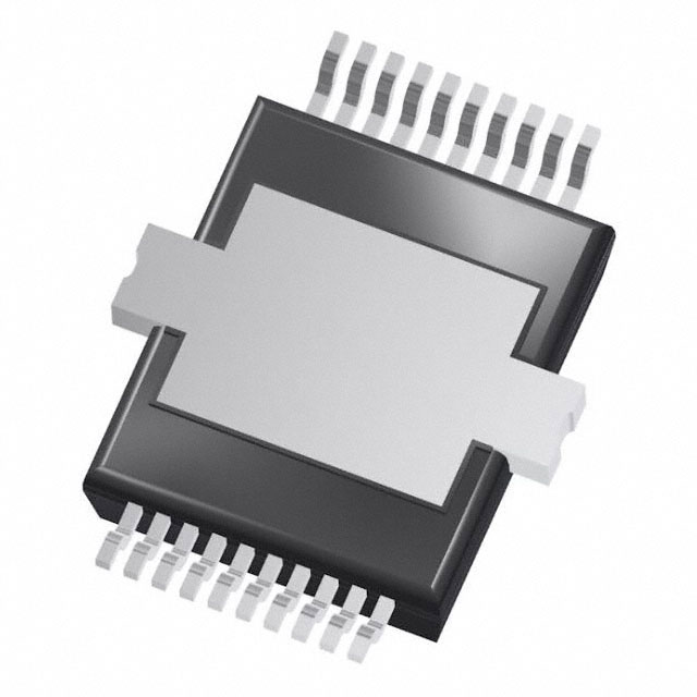
TLE9104SH
Smart Qu ad Channel Powertrain Swi tch
1
Overview
Features
•
Configurable overcurrent protection
•
Overtemperature protection
•
Open load detection
•
Short circuit to GND detection
•
Electrostatic Discharge (ESD) protection
•
16-Bit SPI (for diagnostic and control)
•
Soldering: Automated Optical Inspection capability (AOI)
•
Green product (completely lead free)
•
AEC qualified
Potential applications
The TLE9104SH is best suited for Automotive Powertrain applications. It can be used as driver IC for inductive
and ohmic actuators such as injectors, solenoids and relays.
Product validation
Qualified for Automotive Applications. Product Validation according to AEC-Q100/101.
Description
Quad Low-Side Switch in Smart Power Technology (SPT) with four open drain DMOS output stages. The
TLE9104SH is protected by embedded protection functions and designed for automotive powertrain
applications. The output stages can be controlled directly by parallel inputs for PWM applications (for
example gasoline multiport injection) or by SPI.
Type
Package
Marking
TLE9104SH
PG-DSO-20-88
TLE9104SH
Datasheet
www.infineon.com
1
Rev. 1.31
2020-09-30
�TLE9104SH
Smart Quad Channel Powertrain Switch
Overview
Table 1
Product summary
Parameter
Symbol
Value, Unit
Signal supply voltage
VIO
3.0…5.5 V
Analog supply voltage
VDD
4.5…5.5 V
Output clamping voltage
VDS(AZ)
50…60 V
Typical On-state resistance CH 1-4
at Tj = 25°C
RDS(ON)
150 mΩ
Typical On-state resistance CH 1-4
at Tj = 150°C
RDS(ON)
300 mΩ
Nominal load current CH 1-4 (continuous)
ID
3A
Short circuit to battery detection threshold CH 1-4
ISCB
5A
Datasheet
2
Rev. 1.31
2020-09-30
�TLE9104SH
Smart Quad Channel Powertrain Switch
Table of contents
1
Overview . . . . . . . . . . . . . . . . . . . . . . . . . . . . . . . . . . . . . . . . . . . . . . . . . . . . . . . . . . . . . . . . . . . . . . . . 1
2
Block diagram . . . . . . . . . . . . . . . . . . . . . . . . . . . . . . . . . . . . . . . . . . . . . . . . . . . . . . . . . . . . . . . . . . . 4
3
3.1
3.2
Pin configuration . . . . . . . . . . . . . . . . . . . . . . . . . . . . . . . . . . . . . . . . . . . . . . . . . . . . . . . . . . . . . . . . . 5
Pin assignment . . . . . . . . . . . . . . . . . . . . . . . . . . . . . . . . . . . . . . . . . . . . . . . . . . . . . . . . . . . . . . . . . . . . . . . . . . . 5
Pin definitions and functions . . . . . . . . . . . . . . . . . . . . . . . . . . . . . . . . . . . . . . . . . . . . . . . . . . . . . . . . . . . . . . 5
4
4.1
4.2
General product characteristics . . . . . . . . . . . . . . . . . . . . . . . . . . . . . . . . . . . . . . . . . . . . . . . . . . . . 7
Absolute maximum ratings . . . . . . . . . . . . . . . . . . . . . . . . . . . . . . . . . . . . . . . . . . . . . . . . . . . . . . . . . . . . . . . . 7
Operating conditions . . . . . . . . . . . . . . . . . . . . . . . . . . . . . . . . . . . . . . . . . . . . . . . . . . . . . . . . . . . . . . . . . . . . . 8
5
5.1
5.2
5.3
5.4
5.4.1
5.4.2
5.4.3
5.5
5.5.1
5.6
Electrical and functional description of blocks . . . . . . . . . . . . . . . . . . . . . . . . . . . . . . . . . . . . . . . . 9
Power supply . . . . . . . . . . . . . . . . . . . . . . . . . . . . . . . . . . . . . . . . . . . . . . . . . . . . . . . . . . . . . . . . . . . . . . . . . . . . 9
Parallel inputs . . . . . . . . . . . . . . . . . . . . . . . . . . . . . . . . . . . . . . . . . . . . . . . . . . . . . . . . . . . . . . . . . . . . . . . . . . . 10
Power stages . . . . . . . . . . . . . . . . . . . . . . . . . . . . . . . . . . . . . . . . . . . . . . . . . . . . . . . . . . . . . . . . . . . . . . . . . . . . 10
Protection functions . . . . . . . . . . . . . . . . . . . . . . . . . . . . . . . . . . . . . . . . . . . . . . . . . . . . . . . . . . . . . . . . . . . . . 12
Overtemperature protection . . . . . . . . . . . . . . . . . . . . . . . . . . . . . . . . . . . . . . . . . . . . . . . . . . . . . . . . . . . . 12
Short circuit to battery protection . . . . . . . . . . . . . . . . . . . . . . . . . . . . . . . . . . . . . . . . . . . . . . . . . . . . . . . 12
Overcurrent protections . . . . . . . . . . . . . . . . . . . . . . . . . . . . . . . . . . . . . . . . . . . . . . . . . . . . . . . . . . . . . . . . 12
Diagnostic functions . . . . . . . . . . . . . . . . . . . . . . . . . . . . . . . . . . . . . . . . . . . . . . . . . . . . . . . . . . . . . . . . . . . . . 12
Output stage status . . . . . . . . . . . . . . . . . . . . . . . . . . . . . . . . . . . . . . . . . . . . . . . . . . . . . . . . . . . . . . . . . . . . 15
Communication watchdog . . . . . . . . . . . . . . . . . . . . . . . . . . . . . . . . . . . . . . . . . . . . . . . . . . . . . . . . . . . . . . . 16
6
6.1
6.2
6.2.1
16 bit SPI interface . . . . . . . . . . . . . . . . . . . . . . . . . . . . . . . . . . . . . . . . . . . . . . . . . . . . . . . . . . . . . .
Electrical characteristics 16 bit SPI interface . . . . . . . . . . . . . . . . . . . . . . . . . . . . . . . . . . . . . . . . . . . . . . . .
SPI registers . . . . . . . . . . . . . . . . . . . . . . . . . . . . . . . . . . . . . . . . . . . . . . . . . . . . . . . . . . . . . . . . . . . . . . . . . . . . .
Registers . . . . . . . . . . . . . . . . . . . . . . . . . . . . . . . . . . . . . . . . . . . . . . . . . . . . . . . . . . . . . . . . . . . . . . . . . . . . . .
7
Package outlines . . . . . . . . . . . . . . . . . . . . . . . . . . . . . . . . . . . . . . . . . . . . . . . . . . . . . . . . . . . . . . . . 32
8
Application information . . . . . . . . . . . . . . . . . . . . . . . . . . . . . . . . . . . . . . . . . . . . . . . . . . . . . . . . . . 33
9
Revision history . . . . . . . . . . . . . . . . . . . . . . . . . . . . . . . . . . . . . . . . . . . . . . . . . . . . . . . . . . . . . . . . . 34
Datasheet
3
17
17
19
22
Rev. 1.31
2020-09-30
�TLE9104SH
Smart Quad Channel Powertrain Switch
Block diagram
2
Block diagram
VDD
EN
VIO
OUT1
IN1
IN2
IN3
OUT2
OUT3
input control
OUT4
IN4
RESN
CSN
SCK
SI
temperature
sensor
reset / stand-by
SPI
hardware
configuration
SO
control,
diagnostic
and
protection
functions
short circuit
detection
gate
control
output monitor
open load
detection
diag nostic registe r
GND
Figure 2-1 Block diagram
Datasheet
4
Rev. 1.31
2020-09-30
�TLE9104SH
Smart Quad Channel Powertrain Switch
Pin configuration
3
Pin configuration
3.1
Pin assignment
(top view)
OUT2
GND
OUT1
GND
IN1
IN3
SO
SI
1
20
2
19
3
18
4
17
5
16
6
15
CSN
SCK
GND
7
14
8
13
IN2
IN4
VDD
VIO
EN
RESN
9
12
GND
OUT3
10
11
OUT4
Figure 3-1 Pin configuration (top view)
3.2
Pin definitions and functions
Table 3-1
Pin configuration
#
Pin Name
Function
1
OUT1
Power Output 1
2
GND
Ground
3
IN1
Input 1
4
IN3
Input 3
5
SO
Serial Data Output
6
SI
Serial Data Input
7
CSN
Serial Chip Select (active low)
8
SCK
Serial Clock
9
GND
Ground
10
OUT3
Power Output 3
11
OUT4
Power Output 4
12
GND
Ground
13
RESN
Reset (active low)
14
EN
Output Enable
15
VIO
Signal Supply Voltage
16
VDD
Analog Supply Voltage
17
IN4
Input 4
18
IN2
Input 2
19
GND
Ground
20
OUT2
Power Output 2
Datasheet
5
Rev. 1.31
2020-09-30
�TLE9104SH
Smart Quad Channel Powertrain Switch
Pin configuration
Notes
1. The exposed pad of TLE9104SH is not connected to ground internally. It is highly recommended to connect the
exposed pad to GND pins externally.
2. Pins 2 and 19 are the ground pins of outputs 1 and 2 and pins 9 and 12 are the ground pins of outputs 3 and 4.
It is highly recommened to connect all GND pins externally.
Datasheet
6
Rev. 1.31
2020-09-30
�TLE9104SH
Smart Quad Channel Powertrain Switch
General product characteristics
4
General product characteristics
4.1
Absolute maximum ratings
Table 4-1
Absolute maximum ratings
Tj = -40°C to +150°C; all voltages with respect to ground, positive current flowing into pin
(unless otherwise specified)
Parameter
Symbol
Values
Min.
Typ. Max.
Unit Note or
Number
Test Condition
Signal supply voltage
VIO
-0.3
–
5.5
V
–
P_4.1.1
Analog supply voltage
VDD
-0.3
–
5.5
V
–
P_4.1.2
Continuous drain source voltage (OUT1
to OUT4)
VDS
-0.3
–
50
V
–
P_4.1.3
Input voltage, all inputs and data
outputs, sense lines
VIN
-0.3
–
VIO + 0.3 V
–
P_4.1.4
Output current per channel1)
ID
0
–
5.6
A
Output ON
P_4.1.5
Maximum voltage for short circuit
protection (single event)2)
VSC, single –
–
30
V
–
P_4.1.6
Electrostatic Discharge voltage - HBM
(human body model)3)
VESD1
-2000 –
2000
V
–
P_4.1.7
Electrostatic Discharge voltage - CDM
(charge device model)4)
VESD2
-500
500
V
–
P_4.1.8
–
1) Output current rating as long as maximum junction temperature is not exceeded. The maximum output current in
the application must be calculated using RthJA depending on mounting conditions.
2) Short circuit is designed to be short circuit robust according to AEC-Q100-012.
3) According to ANSI/ESDA/JEDEC JS-001.
4) According to JESD22-C101.
Notes
1. Stresses above the ones listed here may cause permanent damage to the device. Exposure to absolute
maximum rating conditions for extended periods may affect device reliability.
2. Integrated protection functions are designed to prevent IC destruction under fault conditions described in the
datasheet. Fault conditions are considered as “outside” normal operating range. Protection functions are not
designed for continuous repetitive operation.
Datasheet
7
Rev. 1.31
2020-09-30
�TLE9104SH
Smart Quad Channel Powertrain Switch
General product characteristics
4.2
Operating conditions
Table 4-2
Operating conditions
Parameter
Symbol
Values
Min.
Typ.
Max.
Unit Note or
Test Condition
Number
Maximum output clamping energy,
linearly decreasing current 1) 2)
EAR
14
–
–
mJ
ID(0) = 1.4 A,
TJ(0) = 110°C,
Cycles: 1 billion
P_4.2.6
Maximum output clamping energy,
linearly decreasing current3)
EAS
35
–
–
mJ
TJ = 85°C,
Cycles: 10
P_4.2.13
Maximum output clamping energy,
linearly decreasing current
EAS
25
–
–
mJ
TJ = 145°C,
Cycles: 10
P_4.2.14
1.7 ×
EAR
–
–
mJ
OUT1&2 or OUT3&4, P_4.2.2
ID(0), P = 1.8 × ID(0)
RthJC
–
1
1.25
K/W PV = 3 W,
P_4.2.3
homogenously
distributed between
all output stages
Operating temperature range
Tj
-40
–
150
°C
–
P_4.2.4
Storage temperature range
Tstg
-55
–
150
°C
–
P_4.2.5
Maximum output clamping energy in EAR,p
parallel mode
Thermal resistance
Junction to case
Temperature range
1) Pulse shape represents inductive switch off: ID(t) = ID(0) × (1 - t / tpulse); 0 < t < tpulse
2) The given energy values are based on a cumulative scenario as specified in the Notes column.
3) The given energy values are based on a cumulative scenario as specified in the Notes column.
Note: Within the functional range, the IC operates as described in the circuit description. The electrical
characteristics are specified within the conditions given by the related electrical characteristics table.
Datasheet
8
Rev. 1.31
2020-09-30
�TLE9104SH
Smart Quad Channel Powertrain Switch
Electrical and functional description of blocks
5
Electrical and functional description of blocks
5.1
Power supply
The TLE9104SH is supplied by analog power supply line VDD and signal power supply VIO. A capacitor between
pins VDD to GND and VIO to GND is recommended. After start-up of the power supply, the RESN pin should be
kept low until the Reset Duration Time has expired. This will reset all SPI registers to their default values. In
order to enable the output stages the EN pin has to be kept high and OUT_EN register has to be set.
Table 5-1
Electrical characteristics: power supply
VDD = 4.5 V to 5.5 V, VIO = 3 V to 5.5 V, Tj = -40°C to +150°C, (unless otherwise specified)
all voltages with respect to ground, positive current flowing into pin
Parameter
Symbol
Values
Min. Typ. Max.
Unit Note or
Number
Test Condition
Signal supply voltage
VIO
3
–
5.5
V
–
P_5.1.1
Analog supply voltage
VDD
4.5
–
5.5
V
–
P_5.1.2
Supply current
IDD(on)
–
–
10
mA
–
P_5.1.3
Input low voltage of pin RESN
VRESN(L)
-0.3 –
1
V
–
P_5.1.4
Input high voltage of pin RESN
VRESN(H)
2
VIO + 0.3
V
–
P_5.1.5
Hysteresis voltage of pin RESN
VRESN(Hys) 100 300
500
mV
–
P_5.1.6
Input pull-up current
through pin RESN
IRESN
-100 -65
-30
µA
VRESET = 0 V
P_5.1.7
Reset duration time1)
tRESN(L)
10
–
–
µs
–
P_5.1.8
Input low voltage of pin EN
VEN(L)
-0.3 –
1
V
–
P_5.1.9
Input high voltage of pin EN
VEN(H)
2
VIO + 0.3
V
–
P_5.1.10
Hysteresis voltage of pin EN
VEN(Hys)
100 300
500
mV
–
P_5.1.11
Input pull-down current
through pin EN
IEN
30
100
µA
VEN = 2 V
P_5.1.12
–
–
65
1) For proper startup, after the supply VDD has reached its final voltage, the RESN pin should be held low until the reset
duration time has expired.
Datasheet
9
Rev. 1.31
2020-09-30
�TLE9104SH
Smart Quad Channel Powertrain Switch
Electrical and functional description of blocks
5.2
Parallel inputs
Each input signal controls the output stage of its related channel. For example, IN1 controls OUT1, IN2
controls OUT2 etc. Input signals are active low. Hence, applying a voltage less than VIN(L) to INx turns OUTx on.
It is possible to connect OUT1-2 and OUT3-4 in parallel. For this purpose the right configuration has to be
selected in the CFG register. In this case IN1 controls OUT1-2 and IN3 controls OUT3-4.
Table 5-2
Electrical characteristics: parallel inputs
VDD = 4.5 V to 5.5 V, VIO = 3 V to 5.5 V, Tj = -40°C to +150°C, (unless otherwise specified)
all voltages with respect to ground, positive current flowing into pin (unless for pin SO)
Parameter
Symbol
Values
Min. Typ. Max.
Unit Note or
Number
Test Condition
Input low voltage of pin INx
VIN(L)
-0.3 –
1
V
–
P_5.2.1
Input high voltage of pin INx
VIN(H)
2
VIO +
0.3
V
–
P_5.2.2
Input voltage hysteresis
VIN(Hys)
100 300
500
mV
–
P_5.2.3
Input pull-up current
through pin INx
IIN(L)
-100 -65
-30
µA
VIN = 0 V
P_5.2.4
5.3
Power stages
Table 5-3
Electrical characteristics: power outputs
–
VDD = 4.5 V to 5.5 V, VIO = 3 V to 5.5 V, Tj = -40°C to +150°C, (unless otherwise specified)
all voltages with respect to ground, positive current flowing into pin (unless for pin SO)
Parameter
Symbol
Values
Unit Note or
Number
Test
Condition
Min. Typ. Max.
ON resistance
RDS(ON)
–
150
ON resistance
RDS(ON)
–
300
ON resistance in parallel mode
RDS(ON)
–
ON resistance in parallel mode
RDS(ON)
Output clamping voltage
mΩ TJ = 25°C,
P_5.3.1
350
mΩ TJ = 150°C,
P_5.3.2
75
–
mΩ TJ = 25°C,
P_5.3.3
outputs 1&2 or
3&4 in parallel
–
150
175
mΩ TJ = 150°C,
P_5.3.4
outputs 1&2 or
3&4 in parallel
VDS(AZ)
50
–
60
V
output OFF
P_5.3.5
Output leakage current
ID(lkg)
–
–
10
µA
RESN=0
P_5.3.6
Output off-state current
IOUTx_OFF –
–
30
µA
P_5.3.6
RESN=1,
OUTx_DIAG_EN
=0, VOUTx = 35 V
Turn-on time
tON
15
–
µs
from 50% of INx P_5.3.7
to 20% of Vbat
Datasheet
–
10
Rev. 1.31
2020-09-30
�TLE9104SH
Smart Quad Channel Powertrain Switch
Electrical and functional description of blocks
Table 5-3
Electrical characteristics: power outputs (cont’d)
VDD = 4.5 V to 5.5 V, VIO = 3 V to 5.5 V, Tj = -40°C to +150°C, (unless otherwise specified)
all voltages with respect to ground, positive current flowing into pin (unless for pin SO)
Parameter
Symbol
Unit Note or
Number
Test Condition
Min. Typ. Max.
Turn-off time
tOFF
–
Overtemperature shutdown
threshold
Tj(OT)
165 –
Datasheet
11
Values
15
–
µs
from 50% of INx P_5.3.8
to 80% of Vbat
200
°C
–
P_5.3.9
Rev. 1.31
2020-09-30
�TLE9104SH
Smart Quad Channel Powertrain Switch
Electrical and functional description of blocks
5.4
Protection functions
The TLE9104SH provides embedded protection functions. Integrated protection functions are designed to
prevent IC destruction under fault conditions. Fault conditions are considered “outside” the normal operating
range. Protection functions are not designed for continuous repetitive operation. Following protection
functions are implemented for TLE9104SH:
•
Overtemperature protection (OT).
•
Short circuit to battery protection (SCB).
•
Overcurrent protection (OC).
Note: Integrated protection functions are designed to prevent IC destruction under fault conditions described
in the datasheet. Fault conditions are considered as “outside” normal operating range. Protection
functions are not designed for continuous repetitive operation.
5.4.1
Overtemperature protection
A dedicated temperature sensor for each channel detects if the temperature of its channel exceeds the
overtemperature shutdown threshold. If the channel temperature exceeds the overtemperature shutdown
threshold, the overheated channel is switched off immediately to prevent destruction. The channel can be
turned on again after clearing the overtemperature error; however, if the sensed temperature is still higher
than the overtemperature shutdown threshold the channel will switch off after the filter time tOT.
5.4.2
Short circuit to battery protection
The TLE9104SH is protected in case of short circuit to battery. If the current of an output channel exceeds ISCB,
the respective channel is switched off immediately. The channel can be turned on again after the fault
condition has been removed and the error has been cleared.
5.4.3
Overcurrent protections
The TLE9104SH is protected with configurable overcurrent protection. If the current of an output channel
exceeds IOC, the respective channel is switched off after the filter time td(OC). The channel can be turned on
again after the fault condition has been removed and the error has been cleared. Both current limit threshold
IOC and its filter time td(OC) are configurable via SPI. The filter time, td(OC), and the current limit threshold, IOC, can
only be configured while the output bit, OUT_EN, is low in the SPI register.
5.5
Diagnostic functions
Following diagnosis functions are implemented for all output stages of TLE9104SH:
•
Short to battery detection (SCB) can be detected if stages are turned on.
•
Overtemperature detection (OT) can be detected if stages are turned on.
•
Time based overcurrent detection (OCF) can be detected if stages are turned on.
•
Temperature based overcurrent detection (OCT) can be detected if stages are turned on.
•
Short to GND detection (SCG) can be detected if stages are turned off.
•
Open load detection (OL) can be detected if stages are turned off.
The diagnosis information of TLE9104SH can be accessed via SPI interface. OL and SCG diagnosis are
recognized using two thresholds (VOUTn-SCG and VOUTn-OL). It is also possible to turn off the internal diagnostic
pull-down and pull-up current sources. In this case diagnosis of OL and SCG are deactivated.
Datasheet
12
Rev. 1.31
2020-09-30
�TLE9104SH
Smart Quad Channel Powertrain Switch
Electrical and functional description of blocks
Figure 5-1 Overcurrent and short circuit to battery protection
The fault conditions SCG and OL will not be stored until an integrated filtering time, td(fault), has expired. An
additional blanking time, tb(fault), can be configured in addition to the filter time.The blanking time, tb(fault), can
only be configured while output enable bit, OUT_EN, is low in the SPI register.
Status bit
IPU
Diagnostic
Registers
MUX
OUTn
Latch
VOUTn_OL
IPD
Latch
VOUTn_SCG
gate control
Latch
n
Latch
n
Latch
n
td(OC)
Temp.
Sensor
SCB, OC and OT
Prot ection Functions
IOC
GND
Figure 5-2 Diagnostic functions (overview only)
Datasheet
13
Rev. 1.31
2020-09-30
�TLE9104SH
Smart Quad Channel Powertrain Switch
Electrical and functional description of blocks
IOUTn
IOUTn_DIA_P(max)
Diagnostic pull-down current and OL on
OL
SCG
O.K.
420µA
IOUTn_DIA_P(min)
340µA
0
VOUTn_BIAS
IOUTn_DIA_N(max)
VBAT
VOUTn
-120µA
IOUTn_DIA_N(min)
-180µA
VOUTn_SCG
VOUTn_OL
Figure 5-3 SCG and OL diagnostic function (overview only)
Table 5-4
Electrical characteristics: diagnostic functions
VDD = 4.5 V to 5.5 V, VIO = 3 V to 5.5 V, Tj = -40°C to +150°C, (unless otherwise specified)
all voltages with respect to ground, positive current flowing into pin (unless for pin SO)
Parameter
Symbol
Values
Min.
Typ. Max.
Unit Note or
Test Condition
Number
Open load detection
voltage
VOUTn-OL
0.6 VDD 0.2
–
0.6 VDD +
0.2
V
–
P_5.5.1
Diagnostic pull-down
current
IPD
300
380
450
µA
VOUTn = 0.6 VDD
P_5.5.2
-180
-150 -120
µA
VOUTn = 0.4 VDD
P_5.5.3
–
0.4 VDD +
0.2
V
–
P_5.5.4
P_5.5.5
Diagnostic pull-up current IPU
Short circuit to ground
detection voltage
VOUTn-SCG 0.4 VDD 0.2
Short circuit to battery
detection current
ISCB
4.5
5
5.6
A
–
Short circuit to battery
detection current in
parallel mode
ISCB
9
10
11
A
Outputs 1&2 or
P_5.5.6
outputs 3&4
connected in parallel
Fault filtering time1)
td(fault)
0.015
0.02 0.025
ms
Fault blanking time
tb(fault)
0.16
0.2
0.24
ms
configurable via SPI
P_5.5.8
Fault blanking time
tb(fault)
0.4
0.5
0.60
ms
default value
P_5.5.9
Fault blanking time
tb(fault)
0.8
1
1.2
ms
configurable via SPI
P_5.5.10
Fault blanking time
tb(fault)
1.6
2
2.4
ms
configurable via SPI
P_5.5.11
Overcurrent filtering time td(OC)
0.04
0.06 0.08
ms
default value
P_5.5.12
Overcurrent filtering time td(OC)
0.1
0.12 0.14
ms
configurable via SPI
P_5.5.13
Overcurrent filtering time td(OC)
0.4
0.5
ms
configurable via SPI
P_5.5.14
2)
Datasheet
14
0.6
P_5.5.7
Rev. 1.31
2020-09-30
�TLE9104SH
Smart Quad Channel Powertrain Switch
Electrical and functional description of blocks
Table 5-4
Electrical characteristics: diagnostic functions (cont’d)
VDD = 4.5 V to 5.5 V, VIO = 3 V to 5.5 V, Tj = -40°C to +150°C, (unless otherwise specified)
all voltages with respect to ground, positive current flowing into pin (unless for pin SO)
Parameter
Symbol
Values
Min.
Typ. Max.
Unit Note or
Test Condition
Number
Overcurrent filtering time td(OC)
0.8
1
1.2
ms
configurable via SPI
P_5.5.15
Overcurrent filtering time td(OC)
4
5
6
ms
configurable via SPI
P_5.5.16
Overcurrent filtering time td(OC)
8
10
12
ms
configurable via SPI
P_5.5.17
Overcurrent filtering time td(OC)
16
20
24
ms
configurable via SPI
P_5.5.18
Overcurrent filtering time td(OC)
24
30
36
ms
configurable via SPI
P_5.5.19
Overcurrent threshold
IOC
0.75
1
1.25
A
configurable via SPI
P_5.5.20
Overcurrent threshold
IOC
1.75
2
2.25
A
default value
P_5.5.21
Overcurrent threshold
IOC
2.5
3
3.5
A
configurable via SPI
P_5.5.22
Overcurrent threshold
IOC
3.5
4
4.5
A
configurable via SPI
P_5.5.23
Overcurrent threshold in
parallel mode
IOC
1.35
2
2.5
A
configurable via SPI, P_5.5.24
outputs 1&2 or
outputs 3&4
connected in parallel
Overcurrent threshold in
parallel mode
IOC
3.15
4
4.5
A
default value,
P_5.5.25
outputs 1&2 or
outputs 3&4
connected in parallel
Overcurrent threshold in
parallel mode
IOC
4.5
6
7
A
configurable via SPI, P_5.5.26
outputs 1&2 or
outputs 3&4
connected in parallel
Overcurrent threshold in
parallel mode
IOC
6.3
8
9
A
configurable via SPI, P_5.5.27
outputs 1&2 or
outputs 3&4
connected in parallel
Overtemperature filter
time
tOT
2
3
4
µs
–
P_5.5.28
Short circuit to battery
filter time
tSCB
1.2
–
2
µs
–
P_5.5.28
1) td(fault) is the filter time for open load and short to ground diagnostic functions.
2) td(fault) is the blanking time for open load and short to ground diagnostic functions.
5.5.1
Output stage status
The output of open-load comparator of each channel is directly available via OUTx_STAT bit. This bit can be
used to detect a failure condition in which the channel is turned on by INx or SPI but the power stage remains
switched off. The delay between a turn on via INx or SPI and a change in status bit depends on the output
voltage slew rates and hence on the load itself.
Datasheet
15
Rev. 1.31
2020-09-30
�TLE9104SH
Smart Quad Channel Powertrain Switch
Electrical and functional description of blocks
5.6
Communication watchdog
The TLE9104SH is using the watchdog principle to monitor the SPI communication. In case of no
communication or continuous communication failures all outputs are disabled. In case of a faulty SPI frame
the CWD timer does not retrigger and after the filter time the register CWD-TO is set and can be read as soon
as the SPI is back to normal operation. The watchdog is active by default; however, it can be deactivated via a
SPI command.
The watchdog starts to work as soon as the device has finished start-up and all blocks are released from reset.
If these conditions are met, the watchdog timer tCWD is started. Each correct SPI communication restarts the
tCWD timer. If no valid communication is received within timeout, the tCWD timer will expire and disable all
outputs. For re-enabling, one needs to clear the error and enable outputs via SPI. Outputs will not be enabled
automatically by clearing the error.
The watchdog timer tCWD is configurable via SPI. The watchdog timer tCWD can only be configured while the
output enable bit, OUT_EN, is low in the SPI register.
Following SPI communication issues are detected as failure by the watchdog:
•
No communication
•
Wrong commands
•
Frames not equal to 16 clocks
Table 5-5
Communication watchdog timeout configuration
VDD = 4.5 V to 5.5 V, VIO = 3 V to 5.5 V, Tj = -40°C to +150°C, (unless otherwise specified)
all voltages with respect to ground, positive current flowing into pin (unless for pin SO)
Parameter
Symbol
Unit Note or
Test Condition
Min. Typ. Max.
Communication watchdog timeout
tCWD0
20
25
30
ms
configurable via SPI P_5.6.1
Communication watchdog timeout
tCWD1
40
50
60
ms
default value
Communication watchdog timeout
tCWD2
60
75
90
ms
configurable via SPI P_5.6.3
Datasheet
Values
16
Number
P_5.6.2
Rev. 1.31
2020-09-30
�TLE9104SH
Smart Quad Channel Powertrain Switch
16 bit SPI interface
6
16 bit SPI interface
The diagnostic and control interface is based on a serial peripheral interface (SPI).
The SPI is a full duplex synchronous serial slave interface, which uses four lines: SO, SI, SCK, CSN. Data is
transferred by the lines SI and SO at the data rate given by SCK. The falling edge of CSN indicated the beginning
of a data access. Data is sampled in on line SI at the falling edge of SCK and shifted out on line SO at the rising
edge of SCK. Each access shall be terminated by a rising edge of CSN. A modulo 16 counter ensures that data
is taken only, when a multiple of 16 bits has been transferred.
t CSN (lead)
t
t CSN (td)
CSN (lag)
t SCK (p)
S_CSN
t
SCK(h)
t
SCK (l)
S_SCK
tSI(su)
tSI(h)
S_SI
tSO(en)
t SC(V)
tSO(dis)
S_SO
Timing SPI.vsd
Figure 6-1 SPI timing
6.1
Electrical characteristics 16 bit SPI interface
Table 6-1
Electrical characteristics: 16 bit SPI interface
VDD = 4.5 V to 5.5 V, VIO = 3 V to 5.5 V,Tj = -40°C to +150°C, all voltages with respect to ground, positive current
flowing into pin (unless otherwise specified)
Parameter
Symbol
Values
Min.
Typ.
Max.
Unit
Note or
Number
Test Condition
Input characteristics (CSN, SCK, SI)
L level of pin CSN, SCK, SI
VIO_CSNL
VIO_SCKL
VIO_SIL
-0.3
–
1
V
–
P_6.1.1
H level of pin CSN, SCK, SI
VIO_CSNH
VIO_SCKH
VIO_SIH
2
–
VIO + 0.3 V
–
P_6.1.2
Hysteresis input pins
VIO_CSNHy
VIO_SCKHy
VIO_SIHy
100
300
500
mV
–
P_6.1.3
L level output voltage
VIO_SOL
0
–
1
V
IIO_SO = -2 mA
P_6.1.4
H level output voltage
VIO_SOH
VIO - 0.5 –
VIO + 0.3 –
–
P_6.1.5
Output tristate leakage current
IIO_SOoff
-10
10
–
P_6.1.6
Output characteristics (SO)
Datasheet
–
17
µA
Rev. 1.31
2020-09-30
�TLE9104SH
Smart Quad Channel Powertrain Switch
16 bit SPI interface
Table 6-1
Electrical characteristics: 16 bit SPI interface
VDD = 4.5 V to 5.5 V, VIO = 3 V to 5.5 V,Tj = -40°C to +150°C, all voltages with respect to ground, positive current
flowing into pin (unless otherwise specified)
Parameter
Symbol
Values
Unit
Note or
Number
Test Condition
Min.
Typ.
Max.
Cin
–
6
8
pF
–
P_6.1.13
Serial clock frequency1)
fSCK
0
–
8
MHz
CL = 25 pF
P_6.1.7
Serial clock period
tSCK(P)
125
–
–
ns
–
P_6.1.8
Serial clock high time
tSCK(h)
50
–
–
ns
–
P_6.1.9
Serial clock low time
tSCK(l)
50
–
–
ns
–
P_6.1.10
Enable lead time (falling CSN to
rising SCK)
tCSN(lead)
250
–
–
ns
–
P_6.1.11
Enable lag time (falling SCK to
rising CSN)
tCSN(lag)
250
–
–
ns
–
P_6.1.12
Data setup time (required time SI tSI(su)
to falling SCK)
20
–
–
ns
–
P_6.1.14
Data hold time (falling SCK to SI)
20
–
–
ns
Output enable time (falling CSN to tSO(en)
SO valid)
–
–
200
ns
CL = 25 pF
P_6.1.16
Output disable time (rising CSN to tSO(dis)
SO tri-state)
–
–
200
ns
CL = 25 pF
P_6.1.17
Output data valid time with
capacitive load
–
–
100
ns
CL = 25 pF
P_6.1.18
1
–
100
µs
CL = 25 pF
P_6.1.19
Input capacitance
For CSN, SCK, SI and SO
Timings
tSI(h)
tSO(v)
Transfer delay time (rising CSN to tCSN(td)
falling CSN)
P_6.1.15
1) Maximum SPI clock frequency in the application may be less depending on the load at the SO pin and the
microcontroller SPI peripheral timing requirements.
Datasheet
18
Rev. 1.31
2020-09-30
�TLE9104SH
Smart Quad Channel Powertrain Switch
16 bit SPI interface
6.2
SPI registers
The general SPI frame length is fixed at 16 bits. Bits 0 to 7 of each frame are used as data frame, bits 8 to 10 are
used for address, bit 14 is the parity bit and bit 15 is used to specify a command as read or write. The parity bit
is defined as:
13
b 14 = (1+ b 15 + ∑ bi )mod 2
i=0
(6.1)
MOSI
15
14
R/W Parity
13
12
0
0
11
10
9
8
7
6
5
4
Address
3
2
1
0
1
0
Data
MISO
15
14
13
12
11
Fault
Fault
R/W Parity CommuniGlobal
cation
10
9
8
7
6
5
Address
4
3
2
Data
IN MOSI and MISO a read is defined with a ‘0’ and a write is defined with a ‘1’. Each MISO SPI frame reports the
important system faults as Global or Communication faults in bit 12 and 13 as following:
•
Global fault is asserted (not latching) when the general fault bit in Global_Status register is set.
•
Communication fault is asserted (not latching) when one of the following faults are present:
– Communication error (the same as COM_ERR in Global_Status register)
– Communication watchdog timeout
– Parity error
Besides, global status register stores the faults as following:
•
General fault if at least one of the following faults are present:
– Over-current
– Over-temperature
– Over-temperature during overcurrent
– Short circuit to battery
– Open load
– Short circuit to ground
•
Communication error:
– No communication
– Wrong command
– Frames not equal to 16 bits
•
Parity error
•
Communication watchdog
Datasheet
19
Rev. 1.31
2020-09-30
�TLE9104SH
Smart Quad Channel Powertrain Switch
16 bit SPI interface
Apart from the faults, global register also restores the enable latch signal (EN_Latch) and power on reset latch
(POR_Latch) as following:
•
EN_Latch: This bit has a reset value of ‘0’. After setting the OUT_EN bit this bit changes to ‘1’. This bit shows
whether the output has been enabled (via SPI) at least once since the last clear.
•
POR_Latch: This bit has a reset value of ‘1’. It can be changed to ‘0’ via SPI. Any power on reset will set the
bit back to 1. This can be used to check whether a power on reset has happened since the bit value was
changed to ‘0’.
Datasheet
20
Rev. 1.31
2020-09-30
�TLE9104SH
Smart Quad Channel Powertrain Switch
16 bit SPI interface
Table 6-2
Register Address Space
Module
Base Address
End Address
Note
apb
0H
1FH
–
Table 6-3
Register Overview
Register Short Name
Register Long Name
Offset Address
Page
Number
CTRL
Output control register
00H
22
CFG
Configuration register
01H
24
OFF_DIAG_CFG
Off-state diagnostic configuration register
02H
25
ON_DIAG_CFG
On-state diagnostic configuration register
03H
26
DIAG_OUT_1_2_ON
On-state diagnostic result register OUT1 & OUT2 04H
27
DIAG_OUT_3_4_ON
On-state diagnostic result register OUT3 & OUT4 05H
28
DIAG_OFF
Off-state diagnostic result register
06H
29
GLOBAL_STATUS
Global device status register
07H
30
ICVID
IC Version ID
08H
31
The registers are addressed wordwise.
Table 6-4
Register Overview
Bit type short name
Bit type description
Note
r
read
–
rw
read/write
–
rwc
read and clear on write
clear on write 0
Note: All configurations can only be changed while the OUT_EN bit is cleared.
Datasheet
21
Rev. 1.31
2020-09-30
�TLE9104SH
Smart Quad Channel Powertrain Switch
16 bit SPI interface
6.2.1
Registers
Output control register
CTRL
Offset
Output control register
Reset Value
00H
00H
7
6
5
4
3
2
1
0
OUT4_ON
_S
OUT4_ON
_C
OUT3_ON
_S
OUT3_ON
_C
OUT2_ON
_S
OUT2_ON
_C
OUT1_ON
_S
OUT1_ON
_C
rw
rw
rw
rw
rw
rw
rw
rw
Field
Bits
Type
Description
OUT4_ON_S
7
rw
OUT4 SPI control bit (used if CFG.OUT4_DD = 0)
1D SET, Output 4 set
0D NO_ACTION, Output 4 no action
Reset: 0B
OUT4_ON_C
6
rw
OUT4 SPI control bit (used if CFG.OUT4_DD = 0)
1D CLEAR, Output 4 clear
0D NO_ACTION, Output 4 no action
Reset: 0B
OUT3_ON_S
5
rw
OUT3 SPI control bit (used if CFG.OUT3_DD = 0)
1D SET, Output 3 set
0D NO_ACTION, Output 3 no action
Reset: 0B
OUT3_ON_C
4
rw
OUT3 SPI control bit (used if CFG.OUT3_DD = 0)
1D CLEAR, Output 3 clear
0D NO_ACTION, Output 3 no action
Reset: 0B
OUT2_ON_S
3
rw
OUT2 SPI control bit (used if CFG.OUT2_DD = 0)
1D SET, Output 2 set
0D NO_ACTION, Output 2 no action
Reset: 0B
OUT2_ON_C
2
rw
OUT2 SPI control bit (used if CFG.OUT2_DD = 0)
1D CLEAR, Output 2 clear
0D NO_ACTION, Output 2 no action
Reset: 0B
OUT1_ON_S
1
rw
OUT1 SPI control bit (used if CFG.OUT1_DD = 0)
1D SET, Output 1 set
0D NO_ACTION, Output 1 no action
Reset: 0B
Datasheet
22
Rev. 1.31
2020-09-30
�TLE9104SH
Smart Quad Channel Powertrain Switch
16 bit SPI interface
Field
Bits
Type
Description
OUT1_ON_C
0
rw
OUT1 SPI control bit (used if CFG.OUT1_DD = 0)
1D CLEAR, Output 1 clear
0D NO_ACTION, Output 1 no action
Reset: 0B
Datasheet
23
Rev. 1.31
2020-09-30
�TLE9104SH
Smart Quad Channel Powertrain Switch
16 bit SPI interface
Configuration register
CFG
Offset
Configuration register
7
01H
6
CWD_TIME
Reset Value
8FH
5
4
3
2
1
0
OUT3_4_
PAR
OUT1_2_
PAR
OUT4_DD
OUT3_DD
OUT2_DD
OUT1_DD
Field
Bits
Type
Description
CWD_TIME
7:6
rw
Communication watchdog timeout configuration
3D LONG, 75 ms
2D MEDIUM, 50 ms (default)
1D SHORT, 25 ms
0D DISABLED, Communication watchdog disabled
Reset: 10B
OUT3_4_PAR 5
rw
OUT3-4 parallel mode
1D ENABLED, OUT3-4 parallel mode (controlled by IN3 or
CTRL.OUT3_ON)
0D DISABLED, OUT3, OUT4 controlled separately (default)
Reset: 0B
OUT1_2_PAR 4
rw
OUT1-2 parallel mode
1D ENABLED, OUT1-2 parallel mode (controlled by IN1 or
CTRL.OUT1_ON)
0D DISABLED, OUT1, OUT2 controlled separately (default)
Reset: 0B
OUT4_DD
3
rw
OUT4 direct drive mode
1D ENABLED, OUT4 controlled by IN4 (default)
0D DISABLED, OUT4 controlled by SPI (CTRL.OUT4_ON)
Reset: 1B
OUT3_DD
2
rw
OUT3 direct drive mode
1D ENABLED, OUT3 controlled by IN3 (default)
0D DISABLED, OUT3 controlled by SPI (CTRL.OUT3_ON)
Reset: 1B
OUT2_DD
1
rw
OUT2 direct drive mode
1D ENABLED, OUT2 controlled by IN2 (default)
0D DISABLED, OUT2 controlled by SPI (CTRL.OUT2_ON)
Reset: 1B
OUT1_DD
0
rw
OUT1 direct drive mode
1D ENABLED, OUT1 controlled by IN1 (default)
0D DISABLED, OUT1 controlled by SPI (CTRL.OUT1_ON)
Reset: 1B
Datasheet
24
Rev. 1.31
2020-09-30
�TLE9104SH
Smart Quad Channel Powertrain Switch
16 bit SPI interface
Off-state diagnostic configuration register
OFF_DIAG_CFG
Offset
Off-state diagnostic configuration register
7
6
RES
5
Reset Value
02H
4
DIAG_FILT_CFG
1FH
3
2
1
0
OUT4_DI
AG_EN
OUT3_DI
AG_EN
OUT2_DI
AG_EN
OUT1_DI
AG_EN
Field
Bits
Type
Description
DIAG_FILT_CFG
5:4
rw
Diagnostic filter time configuration
3D 2000_us, 2000 us
2D 1000_us, 1000 us
1D 500_us, 500 us (default)
0D 200_us, 200 us
Reset: 01B
OUT4_DIAG_EN
3
rw
Enable diagnostic current OUT4
1D ON, Diagnostic current ON (default)
0D OFF, Diagnostic current OFF
Reset: 1B
OUT3_DIAG_EN
2
rw
Enable diagnostic current OUT3
1D ON, Diagnostic current ON (default)
0D OFF, Diagnostic current OFF
Reset: 1B
OUT2_DIAG_EN
1
rw
Enable diagnostic current OUT2
1D ON, Diagnostic current ON (default)
0D OFF, Diagnostic current OFF
Reset: 1B
OUT1_DIAG_EN
0
rw
Enable diagnostic current OUT1
1D ON, Diagnostic current ON (default)
0D OFF, Diagnostic current OFF
Reset: 1B
Datasheet
25
Rev. 1.31
2020-09-30
�TLE9104SH
Smart Quad Channel Powertrain Switch
16 bit SPI interface
On-state diagnostic configuration register
ON_DIAG_CFG
Offset
On-state diagnostic configuration register
7
6
5
03H
4
RES
Field
01H
3
OC_FILT_CFG
2
1
0
OC_TH
Type
Description
OC_FILT_CFG 4:2
rw
Overcurrent shut-down delay time (for all channels)
7D 30_ms, 30 ms
6D 20_ms, 20 ms
5D 10_ms, 10 ms
4D 5_ms, 5 ms
3D 1_ms, 1 ms
2D 500_us, 500 us
1D 120_us, 120 us
0D 60_us, 60 us (default)
Reset: 000B
OC_TH
rw
Overcurrent shut-down threshold (for all channels) (d_oc_th)
3D 4000_mA, 4 A
2D 3000_mA, 3
1D 2000_mA, 2 A (default)
0D 1000_mA, 1 A
Reset: 01B
Datasheet
Bits
Reset Value
1:0
26
Rev. 1.31
2020-09-30
�TLE9104SH
Smart Quad Channel Powertrain Switch
16 bit SPI interface
On-state diagnostic result register OUT1 & OUT2
DIAG_OUT_1_2_ON
Offset
On-state diagnostic result register OUT1 &
OUT2
7
6
OUT2_ST
AT
OUT1_ST
AT
5
Reset Value
04H
4
00H
3
DIAG_CH2_ON
2
1
DIAG_CH1_ON
Field
Bits
Type
Description
OUT2_STAT
7
r
Channel 2 output status
1D ON, Channel is ON
0D OFF, Channel is OFF
Reset: 0B
OUT1_STAT
6
r
Channel 1 output status
1D ON, Channel is ON
0D OFF, Channel is OFF
Reset: 0B
DIAG_CH2_ON 5:3
rwc
On-state diagnostic result register - Channel 2
7D UNUSED, unused combination
6D UNUSED, unused combination
5D OT, Overtemperature
4D OC_TIME, Overcurrent timeout
3D OC_OT, Overtemperature during overcurrent
2D SCB, Short to battery
1D NO_FAIL, no failure detected
0D UNKNOWN, no diagnosis done
Reset: 000B
DIAG_CH1_ON 2:0
rwc
On-state diagnostic result register - Channel 1
7D UNUSED, unused combination
6D UNUSED, unused combination
5D OT, Overtemperature
4D OC_TIME, Overcurrent timeout
3D OC_OT, Overtemperature during overcurrent
2D SCB, Short to battery
1D NO_FAIL, no failure detected
0D UNKNOWN, no diagnosis done
Reset: 000B
Datasheet
27
0
Rev. 1.31
2020-09-30
�TLE9104SH
Smart Quad Channel Powertrain Switch
16 bit SPI interface
On-state diagnostic result register OUT3 & OUT4
DIAG_OUT_3_4_ON
Offset
On-state diagnostic result register OUT3 &
OUT4
7
6
OUT4_ST
AT
OUT3_ST
AT
5
Reset Value
05H
4
00H
3
DIAG_CH4_ON
2
1
DIAG_CH3_ON
Field
Bits
Type
Description
OUT4_STAT
7
r
Channel 4 output status
1D ON, Channel is ON
0D OFF, Channel is OFF
Reset: 0B
OUT3_STAT
6
r
Channel 3 output status
1D ON, Channel is ON
0D OFF, Channel is OFF
Reset: 0B
DIAG_CH4_ON 5:3
rwc
On-state diagnostic result register - Channel 4
7D UNUSED, unused combination
6D UNUSED, unused combination
5D OT, Overtemperature
4D OC_TIME, Overcurrent timeout
3D OC_OT, Overtemperature during overcurrent
2D SCB, Short to battery
1D NO_FAIL, no failure detected
0D UNKNOWN, no diagnosis done
Reset: 000B
DIAG_CH3_ON 2:0
rwc
On-state diagnostic result register - Channel 3
7D UNUSED, unused combination
6D UNUSED, unused combination
5D OT, Overtemperature
4D OC_TIME, Overcurrent timeout
3D OC_OT, Overtemperature during overcurrent
2D SCB, Short to battery
1D NO_FAIL, no failure detected
0D UNKNOWN, no diagnosis done
Reset: 000B
Datasheet
28
0
Rev. 1.31
2020-09-30
�TLE9104SH
Smart Quad Channel Powertrain Switch
16 bit SPI interface
Off-state diagnostic result register
DIAG_OFF
Offset
Off-state diagnostic result register
7
6
DIAG_CH4_OFF
Field
06H
4
00H
3
DIAG_CH3_OFF
2
DIAG_CH2_OFF
1
Description
DIAG_CH4_OFF 7:6
rwc
OFF-state diagnostic result register Channel 4
3D SCG, Short to ground
2D OL, Open load
1D NO_FAIL, no failure detected
0D UNKNOWN, no diagnosis done
Reset: 00B
DIAG_CH3_OFF 5:4
rwc
Off-state diagnostic result register Channel 3
3D SCG, Short to ground
2D OL, Open load
1D NO_FAIL, no failure detected
0D UNKNOWN, no diagnosis done
Reset: 00B
DIAG_CH2_OFF 3:2
rwc
Off-state diagnostic result register Channel 2
3D SCG, Short to ground
2D OL, Open load
1D NO_FAIL, no failure detected
0D UNKNOWN, no diagnosis done
Reset: 00B
DIAG_CH1_OFF 1:0
rwc
Off-state diagnostic result register Channel 1
3D SCG, Short to ground
2D OL, Open load
1D NO_FAIL, no failure detected
0D UNKNOWN, no diagnosis done
Reset: 00B
29
0
DIAG_CH1_OFF
Type
Datasheet
Bits
5
Reset Value
Rev. 1.31
2020-09-30
�TLE9104SH
Smart Quad Channel Powertrain Switch
16 bit SPI interface
Global device status register
GLOBAL_STATUS
Offset
Global device status register
Reset Value
07H
01H
7
6
5
4
3
2
1
0
OUT_EN
SPARE
GEN_FAU
LT
COM_ERR
PAR_ERR
CWD_TO
EN_LATC
H
POR_LAT
CH
rw
Field
Bits
Type
Description
OUT_EN
7
rw
OUTx enable bit
1D ENABLED, Output switching enabled
0D DISABLED, Outputs disabled (default)
Reset: 0B
SPARE
6
rw
Spare register for future use
1D GLOBAL_STATUS_SPARE_EN,
0D GLOBAL_STATUS_SPARE_DIS, (default)
Reset: 0B
GEN_FAULT
5
rwc
General fault flag
1D ERR, At least one fault was detected
0D NO_ERR, No fault was detected
Reset: 0B
COM_ERR
4
rwc
Communication Error Flag
1D ERR, At least one communication failure was detected
0D NO_ERR, No communication failure was detected
Reset: 0B
PAR_ERR
3
rwc
Parity Error Flag
1D ERR, At least one parity error was detected
0D NO_ERR, No parity error was detected
Reset: 0B
CWD_TO
2
rwc
Communication watchdog timeout
1D ERR, Communication watchdog timeout occurred
0D NO_ERR, No communication watchdog timeout (default)
Reset: 0B
EN_LATCH
1
rwc
EN Latch
1D EN, Device was enabled since last read-out
0D NO_EN, Device was not enabled since last cleared
Reset: 0B
POR_LATCH
0
rwc
Power-on reset latch
1D POR, Device was reset since last cleared
0D NO_POR, Device was not reset since last cleared
Reset: 1B
Datasheet
30
Rev. 1.31
2020-09-30
�TLE9104SH
Smart Quad Channel Powertrain Switch
16 bit SPI interface
IC Version ID
ICVID
Offset
IC Version ID
Reset Value
08H
7
6
5
4
B1H
3
2
1
0
ICVID
Field
Bits
Type
Description
ICVID
7:0
r
IC Version ID
177D ICVID,
Reset: B1H
Datasheet
31
Rev. 1.31
2020-09-30
�TLE9104SH
Smart Quad Channel Powertrain Switch
Package outlines
7
Package outlines
Figure 7-1 PG-DSO-20-88 (Plastic Dual Small Outline Package) Green Product - Package dimensions are
preliminary and may be updated
Green product (RoHS-compliant)
To meet the world-wide customer requirements for environmentally friendly products and to be compliant
with government regulations the device is available as a green product. Green products are RoHS-compliant
(i.e Pb-free finish on leads and suitable for Pb-free soldering according to IPC/JEDEC J-STD-020).
Floating exposed pad
The exposed pad of TLE9104SH is not connected to the ground internally. It is highly recommended to connect
the exposed pad to GND pins externally.
For further information on alternative packages, please visit our website:
http://www.infineon.com/packages.
Datasheet
32
Dimensions in mm
Rev. 1.31
2020-09-30
�TLE9104SH
Smart Quad Channel Powertrain Switch
Application information
8
Application information
VBAT
Reverse Polarity
Protection
TLF35584
VBAT
47 μF
100 nF
47 μF
100 nF
47 nF
*2
PCBConnector
VDD
VIO
Power
Logic
EN
47 nF
*2
Enable
OUT1
CSN
SCK
22 nF *1
SPI
OUT2
OUT3
SI
SO
OUT4
2nd Generation
TC375
RESN
22 nF *1
Reset
22 nF *1
PCBConnector
IN1
IN2
IN3
Parallel Inputs
AURIX™
22 nF *1
IN4
TLE9104SH
GND
Very good GND-connection;
no bouncing due to load
trancients.
*1 - capacitor located close to the connector
*2 - capacitor located close to the IC
Slug
EXTERNAL COMPONENTS.
Ceramic 22 nF : TDK, Typ C1608X7R2A472K
Ceramic 47 nF : TDK, Typ C1005X7R1C473K
Ceramic 100 nF : TDK, Typ C1608X7R1H104K
Electrolytic 47 μF : Nippon Chemi-Con, Typ MVH50VC220MTPK14
Or similar types to achieve the needed ESD-performance
Figure 8-1 Multi port injection application diagram
Datasheet
33
Rev. 1.31
2020-09-30
�TLE9104SH
Smart Quad Channel Powertrain Switch
Revision history
9
Revision history
Table 9-1
Revision history
Version
Date
Changes
Rev. 1.31
2020-09-30
Update of Output current per channel max. rating to 5.6 A (P_4.1.5)
Rev. 1.3
2020-06-05
Max. value of Short circuit to battery detection current modified
Rev. 1.2
2018-10-26
Changed H level output voltage of SO Pin symbol and minimum value changed
Rev. 1.1
2018-02-15
OC filter times updates in SPI table
Rev. 1.0
2018-02-01
First datasheet release
Datasheet
34
Rev. 1.31
2020-09-30
�Trademarks
All referenced product or service names and trademarks are the property of their respective owners.
Edition 2020-09-30
Published by
Infineon Technologies AG
81726 Munich, Germany
© 2020 Infineon Technologies AG.
All Rights Reserved.
Do you have a question about any
aspect of this document?
Email: erratum@infineon.com
Document reference
Z8F56123922
IMPORTANT NOTICE
The information given in this document shall in no
event be regarded as a guarantee of conditions or
characteristics ("Beschaffenheitsgarantie").
With respect to any examples, hints or any typical
values stated herein and/or any information regarding
the application of the product, Infineon Technologies
hereby disclaims any and all warranties and liabilities
of any kind, including without limitation warranties of
non-infringement of intellectual property rights of any
third party.
In addition, any information given in this document is
subject to customer's compliance with its obligations
stated in this document and any applicable legal
requirements, norms and standards concerning
customer's products and any use of the product of
Infineon Technologies in customer's applications.
The data contained in this document is exclusively
intended for technically trained staff. It is the
responsibility of customer's technical departments to
evaluate the suitability of the product for the intended
application and the completeness of the product
information given in this document with respect to
such application.
For further information on technology, delivery terms
and conditions and prices, please contact the nearest
Infineon Technologies Office (www.infineon.com).
WARNINGS
Due to technical requirements products may contain
dangerous substances. For information on the types
in question please contact your nearest Infineon
Technologies office.
Except as otherwise explicitly approved by Infineon
Technologies in a written document signed by
authorized representatives of Infineon Technologies,
Infineon Technologies’ products may not be used in
any applications where a failure of the product or any
consequences of the use thereof can reasonably be
expected to result in personal injury.
�