TLV4906L
Value Optimized Hall Effect Switch for Industrial and Consumer ApplicationsHigh
Precision Hall Effect Switch
About this document
Overview
The TLV4906L is a high precision Hall Effect Switch
with highly accurate switching thresholds for ambient
operating temperatures up to 85°C.
Features
•
2.7 V to 18 V supply voltage operation.
•
Operation from unregulated power supply.
• High sensitivity and high stability of the magnetic switching points.
• High resistance to mechanical stress by active error compensation.
•
Reverse battery protection (-18 V).
•
Superior temperature stability.
•
Low jitter (typically 1 µs).
•
High ESD performance (± 4 kV HBM).
•
Digital output signal (open-drain).
•
Not suitable for automotive applications
Target applications
The TLV4906L is ideally suited for all industrial and consumer applications that require a high precision
switching thresholds for position sensing. It can be used for example for: security systems, alignment control,
push buttons, keyboards, key switches, machine tools, etc.
Product name
Product type
Ordering code
Package
TLV4906L
Hall Effect Switch
SP000604324
PG-SSO-3-2
Datasheet
www.infineon.com
Please read the Important Notice and Warnings at the end of this document
Rev. 1.2
2020-08
�TLV4906L
Value Optimized Hall Effect Switch for Industrial and Consumer
ApplicationsHigh Precision Hall Effect Switch
Table of contents
Table of contents
About this document . . . . . . . . . . . . . . . . . . . . . . . . . . . . . . . . . . . . . . . . . . . . . . . . . . . . . . . . . . . . . . . . . . . 1
Table of contents . . . . . . . . . . . . . . . . . . . . . . . . . . . . . . . . . . . . . . . . . . . . . . . . . . . . . . . . . . . . . . . . . . . . . . . 2
1
1.1
1.2
Functional description . . . . . . . . . . . . . . . . . . . . . . . . . . . . . . . . . . . . . . . . . . . . . . . . . . . . . . . . . . . . . . . . . . 3
General . . . . . . . . . . . . . . . . . . . . . . . . . . . . . . . . . . . . . . . . . . . . . . . . . . . . . . . . . . . . . . . . . . . . . . . . . . . . . . . . .3
Pin configuration . . . . . . . . . . . . . . . . . . . . . . . . . . . . . . . . . . . . . . . . . . . . . . . . . . . . . . . . . . . . . . . . . . . . . . . . 3
1.3
1.4
1.5
1.6
Pin description . . . . . . . . . . . . . . . . . . . . . . . . . . . . . . . . . . . . . . . . . . . . . . . . . . . . . . . . . . . . . . . . . . . . . . . . . . 3
Block diagram . . . . . . . . . . . . . . . . . . . . . . . . . . . . . . . . . . . . . . . . . . . . . . . . . . . . . . . . . . . . . . . . . . . . . . . . . . .4
Operating modes and states . . . . . . . . . . . . . . . . . . . . . . . . . . . . . . . . . . . . . . . . . . . . . . . . . . . . . . . . . . . . . . 4
Functional block description . . . . . . . . . . . . . . . . . . . . . . . . . . . . . . . . . . . . . . . . . . . . . . . . . . . . . . . . . . . . . 5
2
2.1
2.2
2.3
2.4
Specification . . . . . . . . . . . . . . . . . . . . . . . . . . . . . . . . . . . . . . . . . . . . . . . . . . . . . . . . . . . . . . . . . . . . . . . . . . . 6
Application circuit . . . . . . . . . . . . . . . . . . . . . . . . . . . . . . . . . . . . . . . . . . . . . . . . . . . . . . . . . . . . . . . . . . . . . . . 6
Absolute maximum ratings . . . . . . . . . . . . . . . . . . . . . . . . . . . . . . . . . . . . . . . . . . . . . . . . . . . . . . . . . . . . . . . 6
Operating range . . . . . . . . . . . . . . . . . . . . . . . . . . . . . . . . . . . . . . . . . . . . . . . . . . . . . . . . . . . . . . . . . . . . . . . . . 7
Electrical characteristics . . . . . . . . . . . . . . . . . . . . . . . . . . . . . . . . . . . . . . . . . . . . . . . . . . . . . . . . . . . . . . . . . 8
3
3.1
Package information . . . . . . . . . . . . . . . . . . . . . . . . . . . . . . . . . . . . . . . . . . . . . . . . . . . . . . . . . . . . . . . . . . 10
TLV4906L Package outline . . . . . . . . . . . . . . . . . . . . . . . . . . . . . . . . . . . . . . . . . . . . . . . . . . . . . . . . . . . . . . . 10
4
Revision history . . . . . . . . . . . . . . . . . . . . . . . . . . . . . . . . . . . . . . . . . . . . . . . . . . . . . . . . . . . . . . . . . . . . . . . 12
Disclaimer . . . . . . . . . . . . . . . . . . . . . . . . . . . . . . . . . . . . . . . . . . . . . . . . . . . . . . . . . . . . . . . . . . . . . . . . . . . . 13
Datasheet
2
Rev. 1.2
2020-08
�TLV4906L
Value Optimized Hall Effect Switch for Industrial and Consumer
ApplicationsHigh Precision Hall Effect Switch
1 Functional description
1
Functional description
1.1
General
Precise magnetic switching thresholds and high temperature stability are achieved by active compensation
circuits and chopper techniques on chip. Offset voltages generated by temperature-induced stress or
overmolding are canceled so that high accuracy is achieved. The IC has an open collector output stage with 20
mA current sink capability. A wide operating voltage range from 2.7 V to 18 V with reverse polarity protection
down to -18 V makes the TLV4906L suitable for a wide range of applications. A magnetic south pole with a field
strength above Bop turns the output transistor on (output voltage low) and for a magnetic field below Brp the
output transistor is switched off (output voltage high).
1.2
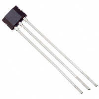
Pin configuration
Center of
Sensitive Area
2.08 ± 0.1
1.35 ± 0.1
1 2 3
PG-SSO-3-2
Figure 1
Pin configuration and sensitive area (Top view, figure not to scale)
1.3
Pin description
Table 1
Pin Definitions for the PG-SSO-3-2 package
Pin No.
Name
Function
1
VS
Supply Voltage
2
GND
Ground
3
Q
Output
Datasheet
3
Rev. 1.2
2020-08
�TLV4906L
Value Optimized Hall Effect Switch for Industrial and Consumer
ApplicationsHigh Precision Hall Effect Switch
1 Functional description
1.4
Block diagram
VS
Voltage Regulator
reverse polarity protected
Bias and
Compensation
Circuits
Oscillator
and
Sequencer
Q
Ref
Amplifier
Chopped
Hall Probe
Low
Pass
Filter
Comparator
with
Hysteresis
Figure 2
TLV4906L Block Diagram
1.5
Operating modes and states
GND
Field direction and definition
Positive magnetic fields correspond to the south pole of the magnet targeting the branded side of the package.
N
S
Branded Side
Optional:
data matrix code
Figure 3
Datasheet
Definition of the magnetic field direction
4
Rev. 1.2
2020-08
�TLV4906L
Value Optimized Hall Effect Switch for Industrial and Consumer
ApplicationsHigh Precision Hall Effect Switch
1 Functional description
VQ
B
0
Brp
Bop
Figure 4
Output signal
1.6
Functional block description
The chopped Hall Effect Switch comprises a Hall probe, a bias generator, compensation circuits, an oscillator
and an output transistor. The bias generator provides currents to the Hall probe and the active circuits.
Compensation circuits stabilize response of the IC over temperature and reduce the impact of process
variations. The Active Error Compensation rejects offsets in the signal path and reduces the impact of
mechanical stress in the package caused by molding, soldering and thermal effects. The chopper technique
together with the threshold generator and the comparator ensure high accurate magnetic switching points.
Datasheet
5
Rev. 1.2
2020-08
�TLV4906L
Value Optimized Hall Effect Switch for Industrial and Consumer
ApplicationsHigh Precision Hall Effect Switch
2.1
Application circuit
TLV4906X
Q
Figure 5
GND
VS
Q
GND
1.2kΩ
Specification
4.7nF
2
4.7nF
2 Specification
200Ω
VS
Application circuit
It is recommended to use a resistor of 200 Ω in the supply line for current limitation in the case of an
overvoltage pulse. Two capacitors of 4.7 nF enhance the EMC performance. The pull-up of 1.2 kΩ limits the
current through the output transistor.
2.2
Absolute maximum ratings
Stress above the maximum values listed in this section may cause permanent damage to the device. Exposure
to absolute maximum rating conditions for extended periods may affect the reliability of the device. Exceeding
only one of these values may cause irreversible damage to the device.
Table 2
Absolute maximum ratings
Parameter
Symbol
Values
Min.
Unit
Typ.
Max.
Maximum Ambient
Temperature
TA
-40
–
125
°C
Maximum Junction
Temperature
TJ
-40
–
150
°C
Supply Voltage
VS
-18
–
18
V
Supply current through
protection device
IS
-50
–
50
mA
Output Voltage
VOUT
-0.7
–
18
V
Storage Temperature
TS
-40
–
150
°C
Magnetic flux density
B
–
–
unlimit mT
ed
–
–
4
ESD Robustness HBM: 1.5 kΩ, VESD,HBM(1)
100 pF
(1)
Note/Test
Condition
kV
According to EIA/JESD22-A114-E
Datasheet
6
Rev. 1.2
2020-08
�TLV4906L
Value Optimized Hall Effect Switch for Industrial and Consumer
ApplicationsHigh Precision Hall Effect Switch
2 Specification
2.3
Operating range
The following operating conditions must not be exceeded in order to ensure correct operation of the TLV4906L.
All parameters specified in the following sections refer to these operating conditions unless otherwise
mentioned.
Table 3
Parameter
Operating range
Symbol
Values
Min.
Typ.
Unit
Max.
Supply Voltage
VS
2.7
–
18
V
Output Voltage
VQ
-0.7
–
18
V
Output Current
IQ
0
–
20
mA
Maximum Ambient
Temperature
TA
-40
–
85
°C
Datasheet
7
Note/Test
Condition
Rev. 1.2
2020-08
�TLV4906L
Value Optimized Hall Effect Switch for Industrial and Consumer
ApplicationsHigh Precision Hall Effect Switch
2 Specification
2.4
Electrical characteristics
Product characteristics include the spread of values guaranteed within the specified voltage and ambient
temperature range. typical characteristics are the median of the production (at VS = 12 V and TA = 25°C).
Table 4
Electrical characteristics
Parameter
Symbol
Values
Min.
Typ.
Unit
Note or Test
Condition
Max.
Supply Current
IS
2
4
6
mA
VS = 2.7 V … 18 V
Reverse Current
ISR
0
0.2
1
mA
VS = -18 V
Output Saturation Voltage
VQSAT
–
0.3
0.6
V
IQ = 20 mA
Output leakage current
IQLEAK
–
0.05
10
µA
VQ = 18 V
Output fall time(1)
tf
–
0.02
1
µs
Output rise time(1)
tr
–
0.4
1
µs
RL = 1.2 kΩ, CL =
50 pF
Chopper frequency
fOSC
–
320
–
kHz
Switching frequency
fSW
0
–
15(2)
kHz
Delay time(3)
td
–
13
–
µs
Output jitter(4)
tQJ
–
1
–
µsRMS Typical value for a
1 kHz square
wave signal
Power-on Time(5)
tPON
–
13
–
µs
VS > 2.7 V
Thermal Resistance junction
to ambient(6)
RthJA
–
–
190
K/W
TLV4906L
(1)
(2)
(3)
(4)
(5)
(6)
See Figure 6
To operate the sensor at maximum switching frequency, the value of the magnetic signal amplitude must
be 1.4 times higher than the static fields. This is due to the -3 dB corner frequency of the low pass filter in
the signal path.
Systematic delay between magnetic threshold reached and output.
Jitter is the unpredictable deviation of the output switching delay.
Time from applying VS > 2.7 V to the sensor until the output state is valid.
Relationship between junction and ambient temperature: TJ = Tamb + Rthja . (VS . IS + VQS . IQ).
Datasheet
8
Rev. 1.2
2020-08
�TLV4906L
Value Optimized Hall Effect Switch for Industrial and Consumer
ApplicationsHigh Precision Hall Effect Switch
2 Specification
BOP
Applied
Magnetic
Field
BRP
td
VQ
td
tf
tr
90%
10%
Figure 6
Timing diagram
Table 5
Magnetic characteristics(1)
Parameter
Symbol
Values
Min.
Unit
Typ.
Max.
Note/Test
Condition
Operate point
BOP
6.2
10.0
13.9
mT
Release point
BRP
4.7
8.5
12.3
mT
Hysteresis
BHYS
0.7
1.5
3.0
mT
Temperature compensation
of magnetic thresholds
TC
–
-350
–
ppm/°
C
Repeatability of magnetic
thresholds(3) BREP is
equivalent to the noise
constant.
BREP
–
20
–
µTRMS typical value for
ΔΒ/Δt > 12 mT/ms
(1)
(2)
(3)
(2)
Over all operating conditions.
At 25°C.
Datasheet
9
Rev. 1.2
2020-08
�TLV4906L
Value Optimized Hall Effect Switch for Industrial and Consumer
ApplicationsHigh Precision Hall Effect Switch
3 Package information
3
Package information
3.1
TLV4906L Package outline
VB1
yww S
d
optional:
data matrix code
Year (y) = 0...9
Calendar Week (ww) = 01...52
Branded Side
Hall-Probe
d : Distance chip to upper side of IC
PG-SSO-3-2 : 0.57 ±0.8 mm
Figure 7
Datasheet
Marking of the TLV4906L and distance of the chip to the upper side
10
Rev. 1.2
2020-08
�TLV4906L
Value Optimized Hall Effect Switch for Industrial and Consumer
ApplicationsHigh Precision Hall Effect Switch
3 Package information
0.8 ±0.1 x 45°
0.2
2 A
1.52 ±0.05
1 MAX.1)
7°
3 ±0.06
1.9 MAX.
0.35 ±0.1 x 45°
4.06 ±0.08
3.29 ±0.08
4.16 ±0.05
(0.25)
0.15 MAX.
7°
(0.79)
0.6 MAX.
0.2 +0.1
0.4 ±0.05
1.27±0.25
1
2
3
1.27±0.25
18 ±0.5
6 ±0.5
1-1
38 MAX.
9 +0.75
-0.5
23.8 ±0.5
12.7 ±1
A
+
Adhesive
Tape
Tape
6.35 ±0.4
1) No solder function area
Figure 8
Datasheet
4 ±0.3
12.7 ±0.3
Total tolerance at 10 pitches ±1
0.25 -0.15
0.39 ±0.1
GPO05358
PG-SSO-3-2 Package outline
11
Rev. 1.2
2020-08
�TLV4906L
Value Optimized Hall Effect Switch for Industrial and Consumer
ApplicationsHigh Precision Hall Effect Switch
4 Revision history
4
Revision history
Revision History
Page
Subjects (major changes since last revision)
Revision History: 2020-08, Rev. 1.2
Previous Revisions: 1.1
9
Datasheet
Edited figure 7 (optional: data matrix code)
12
Rev. 1.2
2020-08
�Trademarks
All referenced product or service names and trademarks are the property of their respective owners.
Edition 2020-08
Published by
Infineon Technologies AG
81726 Munich, Germany
© 2020 Infineon Technologies AG
All Rights Reserved.
Do you have a question about any
aspect of this document?
Email: erratum@infineon.com
Document reference
IFX-mok1599123596500
IMPORTANT NOTICE
The information given in this document shall in no
event be regarded as a guarantee of conditions or
characteristics (“Beschaffenheitsgarantie”) .
With respect to any examples, hints or any typical
values stated herein and/or any information regarding
the application of the product, Infineon Technologies
hereby disclaims any and all warranties and liabilities
of any kind, including without limitation warranties of
non-infringement of intellectual property rights of any
third party.
In addition, any information given in this document is
subject to customer’s compliance with its obligations
stated in this document and any applicable legal
requirements, norms and standards concerning
customer’s products and any use of the product of
Infineon Technologies in customer’s applications.
The data contained in this document is exclusively
intended for technically trained staff. It is the
responsibility of customer’s technical departments to
evaluate the suitability of the product for the intended
application and the completeness of the product
information given in this document with respect to such
application.
WARNINGS
Due to technical requirements products may contain
dangerous substances. For information on the types
in question please contact your nearest Infineon
Technologies office.
Except as otherwise explicitly approved by Infineon
Technologies in a written document signed by
authorized representatives of Infineon Technologies,
Infineon Technologies’ products may not be used in
any applications where a failure of the product or
any consequences of the use thereof can reasonably
be expected to result in personal injury.
�
很抱歉,暂时无法提供与“TLV4906L”相匹配的价格&库存,您可以联系我们找货
免费人工找货