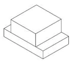
SURFACE MOUNT LED LAMP
0603 (0.6 mm Height)
Low VF Blue
QTLP601CEBTR
PACKAGE DIMENSIONS
0.071 (1.8)
0.055 (1.4)
0.035 (0.9)
0.028 (0.7)
TOP
0.047 (1.2)
0.006 (0.15)
0.024 (0.6)
SIDE
0.039 (1.0)
CATHODE MARK
BOTTOM
-
+
POLARITY
APPLICATIONS
NOTE:
-Dimensions for all drawings are in inches (mm).
-Tolerance is ±0.1mm unless otherwise noted.
• Keypad backlighting
• Push-button backlighting
• LCD backlighting
DESCRIPTION
This surface mount chip LED is designed to fit industry standard footprint. Small size, low profile and wide viewing angle make this
LED an ideal choice for backlighting applications and panel illumination. This device utilizes an InGaN/Sapphire blue LED.
FEATURES
• Miniature footprint - 1.6(L) X 0.8(W) X 0.6(H) mm
• Wide viewing angle of 120°
• Water clear optics
• Moisture-proof packaging
• Available in 0.315" (8mm) width tape on 7" (178mm) diameter reel; 2,000 units per reel
© 2004 Fairchild Semiconductor Corporation
Page 1 of 6
4/29/04
�SURFACE MOUNT LED LAMP
0603 (0.6 mm Height)
Low VF Blue
QTLP601CEBTR
ABSOLUTE MAXIMUM RATINGS (TA = 25°C unless otherwise specified)
Parameter
Symbol
Rating
Unit
Operating Temperature
TOPR
-40 to +85
°C
Storage Temperature
TSTG
-40 to +90
°C
Lead Soldering Time
TSOL
260 for 5 sec
°C
IF
30
mA
Peak Forward Current
(f = 1.0 KHz, Duty Factor = 1/10)
IFM
100
mA
Reverse Voltage
VR
5
V
Power Dissipation
PD
80
mW
Continuous Forward Current
ELECTRICAL / OPTICAL CHARACTERISTICS (TA =25°C)
Part Number
QTLP601CEBTR
Condition
Bin I1
8 - 16
IF = 5 mA
Bin I2
13 - 26
Luminous Intensity (mcd)
Forward Voltage (V)
Bin V0
2.55 - 2.75
Bin V1
2.75 - 2.95
Bin V2
2.95 - 3.15
Bin V3
3.15 - 3.35
Bin V4
3.35 - 3.55
Bin V5
3.55 - 3.75
IF = 5 mA
Dominant Wavelength (nm)
Bin W1
465 - 470
Bin W2
470 - 475
Bin W3
475 - 480
Reverse Current (IR) max:
IF = 5 mA
50 µA
VR = 5 V
Spectral Line Half Width (nm)
35
IF = 5 mA
Viewing Angle (°)
120
IF = 5 mA
Measurement uncertainty of luminous intensity is ±11%
© 2004 Fairchild Semiconductor Corporation
Page 2 of 6
4/29/04
�SURFACE MOUNT LED LAMP
0603 (0.6 mm Height)
Low VF Blue
QTLP601CEBTR
TYPICAL PERFORMANCE CURVES
Fig. 2 Relative Luminous Intensity vs.
DC Forward Current
Fig. 1 Forward Current vs. Forward Voltage
1.4
RELATIVE LUMNOUS INTENSITY
(NORMALIZED AT 20 mA)
IF - FORWARD CURRENT (mA)
100
10
1
0.1
2.00
1.2
1.0
0.8
0.6
0.4
0.2
0.0
2.50
3.00
3.50
0
4.00
10
20
40
30
IF - FORWARD CURRENT (mA)
VF - FORWARD VOLTAGE (V)
Fig. 3 Relative Intensity vs. Peak Wavelength
RELATIVE INTENSITY
1.0
0.5
0
300
350
400
450
500
550
600
650
700
750
WAVELENGTH (nm)
Fig.5 Maximum Forward Current
vs. Ambient Temperature
IF - FORWARD CURRENT (mA)
50
Fig.4 Radiation Diagram
-30˚
-20˚
-10˚ 0˚ 10˚
20˚
30˚
-40˚
40˚
-50˚
50˚
-60˚
60˚
-70˚
70˚
-80˚
-90˚
1.0
40
30
20
10
80˚
0.8
0.6 0.4
0.2
0
0.2
0.4 0.6
0.8
1.0
0
90˚
0
40
60
80
100
TA - AMBIENT TEMPERATURE (˚C)
REL. LUMINOUS INTENSITY (%)
© 2004 Fairchild Semiconductor Corporation
20
Page 3 of 6
4/29/04
�SURFACE MOUNT LED LAMP
0603 (0.6 mm Height)
Low VF Blue
QTLP601CEBTR
RECOMMENDED PRINTED CIRCUIT BOARD PATTERN
0.033 (0.85)
0.031 (0.80)
0.031 (0.80)
0.039 (1.00)
RECOMMENDED IR REFLOW SOLDERING PROFILE
5 sec MAX
soldering time
240° C MAX
+5° C/s MAX
-5° C/s MAX
60 - 120 sec
Preheating
120 - 150° C MAX
© 2004 Fairchild Semiconductor Corporation
Page 4 of 6
4/29/04
�SURFACE MOUNT LED LAMP
0603 (0.6 mm Height)
Low VF Blue
QTLP601CEBTR
TAPE AND REEL DIMENSIONS
8.4
+1.5
-0.0
11.0
Ø62.0±0.5
2.5
0±
0.5
Ø180±1
5
±0.
2.5
+0.5
-0.0
Ø12.75
+0.25
-0.0
4.0
0.23±0.1
Ø1.55.±05
1.8±0.1
2.0±0.05
8.0
3.5±0.05
1.75
Progressive direction
4.0
0.9
0.7
Dimensional tolerance is ± 0.1mm unless otherwise specified
Angle: ± 0.5
Polarity
Unit: mm
© 2004 Fairchild Semiconductor Corporation
Page 5 of 6
4/29/04
�SURFACE MOUNT LED LAMP
0603 (0.6 mm Height)
Low VF Blue
QTLP601CEBTR
DISCLAIMER
FAIRCHILD SEMICONDUCTOR RESERVES THE RIGHT TO MAKE CHANGES WITHOUT FURTHER NOTICE TO
ANY PRODUCTS HEREIN TO IMPROVE RELIABILITY, FUNCTION OR DESIGN. FAIRCHILD DOES NOT ASSUME
ANY LIABILITY ARISING OUT OF THE APPLICATION OR USE OF ANY PRODUCT OR CIRCUIT DESCRIBED HEREIN;
NEITHER DOES IT CONVEY ANY LICENSE UNDER ITS PATENT RIGHTS, NOR THE RIGHTS OF OTHERS.
LIFE SUPPORT POLICY
FAIRCHILD’S PRODUCTS ARE NOT AUTHORIZED FOR USE AS CRITICAL COMPONENTS IN LIFE SUPPORT DEVICES
OR SYSTEMS WITHOUT THE EXPRESS WRITTEN APPROVAL OF THE PRESIDENT OF FAIRCHILD SEMICONDUCTOR
CORPORATION. As used herein:
1. Life support devices or systems are devices or systems
which, (a) are intended for surgical implant into the body, or
(b) support or sustain life, and (c) whose failure to perform
when properly used in accordance with instructions for use
provided in the labeling, can be reasonably expected to
result in a significant injury of the user.
© 2004 Fairchild Semiconductor Corporation
2. A critical component in any component of a life support
device or system whose failure to perform can be
reasonably expected to cause the failure of the life support
device or system, or to affect its safety or effectiveness.
Page 6 of 6
4/29/04
�
很抱歉,暂时无法提供与“QTLP601CEBTR”相匹配的价格&库存,您可以联系我们找货
免费人工找货