SP619
High Current Power Switch
FEATURES
• Max Rds(on) .377 Ohms
• Overcurrent deactivation 800mA
• Max leakage current less than 2µA
while deactivated
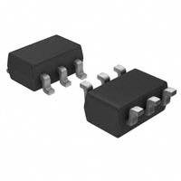
• Small 6 pin SOT-23 package
• Built-in Over-temperature Protection
• 4.5V to 5.5V Input voltage range
6
5
4
SP619
SOT23-6
APPLICATIONS
• Ultra low cost handsets
• PDA, DSC, MP3 players
• Cell phones
• Power Distribution Switch
• Battery-Charger Circuit
1
2
3
DESCRIPTION
The SP619 is a low RDS(ON) high current switch designed with precision current limiting to protect connected devices from damage due to a short circuit condition or
against current surges that may cause the supply voltages to fall out of regulation.
This switch is functional over an input voltage range of 2.5V to 7V, but is targeted
at 5V applications. The SP619 is also protected from thermal overload which limits
power dissipation. In shutdown mode, the supply current drops to 2µA.
TYPICAL APPLICATION CIRCUIT
Vin
SP619
Vout
Vin
100K
Cin .1µF
Cout
.1µF
LOAD
EN
ON/OFF
80K
Aug24-17 Rev M
GND
SP619 High Current Power Switch
1
�ABSOLUTE MAXIMUM RATINGS
These are stress ratings only and functional operation of the device at these ratings or any other
above those indicated in the operation sections of
the specifications below is not implied. Exposure to
absolute maximum rating conditions for extended
periods of time may affect reliability.
Vin……….…………………………….….…-0.3V to 7V
Storage Temperature..…....……….… -65°C to 150°C
Junction Temperature..................... ……..…….150°C
Lead Temperature (Soldering, 10 sec)......…….300°C
ESD RATING
Human Body Model……………………….…….2000V
Machine Model…………………………………....200V
OPERATING RATINGS
Thermal resistance SOT23-6
Junction to Ambient……………………….….….191°C
Junction to lead ……………………...……………50°C
RECOMMENDED OPERATING CONDITIONS
Unless otherwise specified: Vin = 4.5V - 5.5V, Cin = 0.1µF, Ta = -10°C to + 85°C
PARAMETER
CONDITIONS
MIN
Operating Input Voltage
Range
TYP (Note 1)
4.5
Overcurrent Deactivation
Range
EN=1.5V
620
Overcurrent Duration Before Deactivation
EN=1.5V
1
800
MAX
UNITS
5.5
V
1010
mA
5.25
ms
Shutdown Supply Current
Vin=4.5V
2
µA
Quiescent Supply Current
EN=1.5V Vin=4.5V
Iout=0mA
350
µA
Quiescent Supply Current
EN=1.5V Vin=4.5V
Iout=725mA
5.25
mA
Vin=4.5V Iout=100mA
EN=1.5V
.377
Ω
23
KΩ
55
ms
Rds(on)
Post Fault Output Load for
Recovery
Enable=1.5V
10
Post Fault Activation Turn
On Time
Enable=1.5V
1
SP619 will self recover
when temperature drops
below the trip point .
120
150
180
°C
90
120
135
°C
Thermal Shutdown Die
Temperature
Thermal Restart Die Temperature
ENABLE Logic LOW
ENABLE Pin Logic HIGH
Driver is disabled
Driver is active
.655
15
.5
V
1.4
V
Turn On Delay
Rl=100kΩ, Cl= 0.01µF
(Note 2,3)
600
µs
Turn Off Delay
Rl=100kΩ, Cl= 0.01µF
(Note 2,4)
200
µs
Rise Time
Rl=100kΩ, Cl= 0.01µF
(Note 2)
100
µs
Fall Time
Rl=100kΩ, Cl= 0.01µF
(Note 2)
2500
µs
Note 1: Typicals are Tj=25°C
Note 2: Characterized, not 100% tested
Note 3: Turn on delay is measured from the time the enable pin is turned on to the time it takes the output to rise to 10% of its
final value.
Note 4: Turn off delay is measured from the time the enable pin is turned to the time it takes for the output to fall to 90% of its
current value.
Aug24-17 Rev M
SP619 High Current Power Switch
2
�FAULT AND RECOVERY TRUTH TABLE*
Enable
Load
Temperature
(TJ)
Previous
State
Switch
Current State/Fault
(Note*)
Low
X
X
X
Open
Off
High
< 800 mA
< 163ºC
Off
Closed
Normal
High
< 800 mA
> 163ºC
Off
Open
Thermal Cutoff
High
> 800 mA
< 163ºC
Off
Open
Overcurrent
High
> 800 mA
> 163ºC
Off
Open
Thermal Cutoff,
Overcurrent
High
< 15kΩ
< 163ºC
Overcurrent
Open
Load Condition
High
< 15kΩ
> 163ºC
Overcurrent
Open
Thermal Cutoff,
Overcurrent, Load
Condition
High
> 15kΩ
< 163ºC
Overcurrent
Closed
Normal
High
> 15kΩ
> 163ºC
Overcurrent
Open
Thermal Cutoff
High
< 15kΩ
< 120ºC
Thermal Cutoff
Open
Load Condition
High
< 15kΩ
> 120ºC
Thermal Cutoff
Open
Load Condition,
Thermal Cutoff
High
> 15kΩ
< 120ºC
Thermal Cutoff
Closed
Normal
High
> 15kΩ
> 120ºC
Thermal Cutoff
Open
Thermal Cutoff
*Note: This table is for fault conditions, not for continuous operation, else damage to the device may
occur. In order to recover to the normal state after a Thermal Cutoff fault, the part’s junction temperature must decrease below 120ºC and the load on its output must be greater than 15kΩ.
PIN ASSIGNMENTS
PIN
NUMBER
PIN
NAME
FUNCTION
1
Vin
Input power supply pin (4.5V to 5.5V)
2
GND
Ground connection
3
Enable
A logic high turns on the switch
4
NC
No connect
5
NC
No connect
6
Vout
Switch output
Aug24-17 Rev M
SP619 High Current Power Switch
3
�THEORY OF OPERATION
The SP619 is a switch capable of handling
up to 800mA of current.
inrush current that can be encountered.
At 6 volts in, the inrush current was about
250mA into a 100µF capacitor.
The SP619 is targeted as a 5V USB
protection power distribution switch. And
can be used in general power distribution
applications where short circuits are likely
to be encountered.
Output Voltage Rise Time
The output voltage of the SP619 has an
output capacitance dependency on the
slope of Vout. A simple RC circuit is created when the switch is turned on.
Equation 1
Short circuit operation
When the SP619 enters a short circuit condition, the switch is disabled. The output
of the SP619 will not restart until the output impedance is greater than 15KΩ. The
enable pin can be used to re-enable the
SP619 into any load condition that is not a
fault condition. Refer to the truth table on
page 4 for more information on the different
SP619 switch states. The typical deactivation time is about 2ms.
(
V(t)=Vo+Vin
-t
Rds(on) • Cout
1-e
(
Where Vo is initial Voltage condition typically 0V
Vin is the input voltage
Rds(on) is the switch resistance
Cout is the output capacitance
For 4.2V Vin and 100µF output capacitance
we get about 150ns delay in figure 2.
Enable
The enable pin allows easy control of
the SP619. The enable pin should not
be enabled high prior to a voltage being
present on the input of the device. The
enable pin should not exceed the input voltage by more than 0.1V due to an
internal ESD diode. Doing so will affect the
operation of the SP619 and could damage
the device. In a typical application an 80KΩ
resistor to GND should be used on the
enable pin. This resistor will pull the enable
low when an enable signal is not present.
This prevents the SP619 from falsely turning on. The enable pin can also be used
to restart the part into a load condition that
is high in current. Please refer to the truth
table on page 4 for more details.
4.17
3.33
VOUT 2.5
1.67
0.83
0
0
0.33
0.67
1
time in uS
1.33
1.67
2
This is comparable to actual measured
value in figure 3.
Inrush Current
The SP619 is a simple resistive switch.
When the switch is turned on into a highly
capacitive load there could be a significant
Aug24-17 Rev M
SP619 High Current Power Switch
4
�THEORY OF OPERATION
Overtemperature Protection
The SP619 has built-in overtemperature
protection to protect the part against damage if the die temperature gets too hot. The
typical thermal cutoff is about 150ºC. The
part will self recover if the temperature drops
below the thermal restart threshold of about
120ºC.
Layout Considerations
The input and output decoupling capacitors
should be placed as close as possible to the
input and output pins. The GND pin should
be stitched to the GND plain to help with
thermal performance. The input and output
traces should be as large as possible. The
100KΩ is also recommended in the design
and should be placed close to the output decoupling cap.
146-6642-00
Vin
U1 Vout
ON/OFF
GND
Solved by
TM
SP619
Recommended Layout
Aug24-17 Rev M
SP619 High Current Power Switch
5
�6 PIN SOT-23
Aug24-17 Rev M
SP619 High Current Power Switch
6
�ORDERING INFORMATION(1)
Part number
Operating
Temperature
Range
SP619EK-L/TR(3)
-10 to +85ºC
SP619EK-L/TRR3
-10 to +85ºC
Lead-Free
Package
Type
Yes(2)
6 pin SOT23
Packaging Method
Tape and Reel
Tape and Reel
(reverse orientation)
NOTE:
1. Refer to www.exar.com/SP619 for most up-to-date Ordering Information
2. Visit www.exar.com for additional information on Environmental Rating.
3. NRND - Not recommended for new designs.
Corporate Headquarters:
5966 La Place Court
Suite 100
Carlsbad, CA 92008
Tel.:+1 (760) 692-0711
Fax: +1 (760) 444-8598
www.maxlinear.com
High Performance Analog:
48720 Kato Road
Fremont, CA 94538
Tel.: +1 (510) 668-7000
Fax: +1 (510) 668-7001
Email: powertechsupport@exar.com
www.exar.com
The content of this document is furnished for informational use only, is subject to change without notice, and should not be construed as a commitment
by MaxLinear, Inc.. MaxLinear, Inc. assumes no responsibility or liability for any errors or inaccuracies that may appear in the informational content
contained in this guide. Complying with all applicable copyright laws is the responsibility of the user. Without limiting the rights under copyright, no
part of this document may be reproduced into, stored in, or introduced into a retrieval system, or transmitted in any form or by any means (electronic,
mechanical, photocopying, recording, or otherwise), or for any purpose, without the express written permission of MaxLinear, Inc.
Maxlinear, Inc. does not recommend the use of any of its products in life support applications where the failure or malfunction of the product can
reasonably be expected to cause failure of the life support system or to significantly affect its safety or effectiveness. Products are not authorized
for use in such applications unless MaxLinear, Inc. receives, in writing, assurances to its satisfaction that: (a) the risk of injury or damage has been
minimized; (b) the user assumes all such risks; (c) potential liability of MaxLinear, Inc. is adequately protected under the circumstances.
MaxLinear, Inc. may have patents, patent applications, trademarks, copyrights, or other intellectual property rights covering subject matter in this
document. Except as expressly provided in any written license agreement from MaxLinear, Inc., the furnishing of this document does not give you
any license to these patents, trademarks, copyrights, or other intellectual property.
Company and product names may be registered trademarks or trademarks of the respective owners with which they are associated.
© 2008 - 2017 MaxLinear, Inc. All rights reserved
Aug24-17 Rev M
SP619 High Current Power Switch
7
�