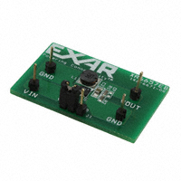
XRP6657
1.5A 1.3MHz Synchronous Step Down Converter
February 2012
Rev. 1.1.0
GENERAL DESCRIPTION
EVALUATION BOARD MANUAL
The XRP6657 Evaluation Board is designed to
help the user evaluate the performance of the
XRP6657 for use as a single Li-Ion battery
Step-Down DC-DC Converter.
The XRP6657 operates from 2.5V to 5.5V
input, with the highest efficiency in the range
3.0V to 4.2V where the Li-Ion battery has the
most energy.
The XRP6657 evaluation board is a complete
power supply circuit to provide ease of
evaluation
for
the
DC/DC
converter
performance. The Evaluation Board schematic
diagram is shown in Figure 1.
FEATURES
Guaranteed 1.5A Output Current
Fixed 1.3MHz Frequency PWM Operations
Up to 95% efficiency
Adjustable Output Voltage
Internal Compensation Network
No Schottky Diode Required
LDO Operation: 100% Duty Cycle
Over-current/Over-temperature
Protection
“Green”/Halogen Free DFN-6 Package
EVALUATION BOARD SCHEMATICS
Fig. 1: XRP6657 Evaluation Board Schematics
Exar Corporation
48720 Kato Road, Fremont CA 94538, USA
www.exar.com
Tel. +1 510 668-7000 – Fax. +1 510 668-7001
�XRP6657
1.5A 1.3MHz Synchronous Step Down Converter
PIN ASSIGNEMENT
VFB
1
VSS_PWR
2
SW
3
6
EN
XRP6657
DFN-6
5
VIN_CLN
VSS_CLN
4
VIN_PWR
Fig. 2: XRP6657 Pin Assignment
PIN DESCRIPTION
Name
Pin Number
VFB
1
VSS_PWR
2
SW
3
VIN_PWR
4
VIN_CLN
5
EN
6
VSS_CLN
Exposed Pad
Description
Feedback Pin.
Receives the feedback voltage from an external resistive divider across the output.
Power Ground Pin.
Switching node.
Must be connected to inductor. This pin connects to the drains of the internal main
and synchronous power MOSFET switches.
Power Input Pin.
Must be closely decoupled to ground pin with a 4.7µF or greater capacitor.
Analog Input Pin.
Must be closely decoupled to ground pin with a 4.7µF or greater capacitor.
Enable Pin.
>1.2V: Enables the XRP6657
很抱歉,暂时无法提供与“XRP6657EVB”相匹配的价格&库存,您可以联系我们找货
免费人工找货