物料型号:
- 74F157ASC M16A:16-Lead Small Outline Integrated Circuit (SOIC), JEDEC MS-012, 0.150 Narrow
- 74F157ASJ M16D:16-Lead Small Outline Package (SOP), EIAJ TYPE II, 5.3mm Wide
- 74F157APC N16E:16-Lead Plastic Dual-In-Line Package (PDIP), JEDEC MS-001, 0.300 Wide
器件简介:
74F157A是一款高速四路二输入多路选择器。它可以通过共用的Select和Enable输入从两个数据源选择四比特数据。四个输出以真值(非反相)形式呈现所选数据。74F157A还可以用来生成两个变量的16种不同函数中的任意四种。
引脚分配:
| Pin Names | Description | U.L. HIGH/LOW | Input Output loH/loL |
| --- | --- | --- | --- |
| od | Source 0 Data Inputs | 1.0/1.0 | 20 A/-0.6 mA |
| l1a-1d | Source 1 Data Inputs | 1.0/1.0 | 20 A/-0.6 mA |
| E | Enable Input (Active LOW) | 1.0/1.0 | 20 A/-0.6 mA |
| S | Select Input | 1.0/1.0 | 20A/-0.6 mA |
| Za-2 | Outputs | 50/33.3 | -1 mA/20 mA |
参数特性:
- 使能输入(E)为低电平有效。
- 当E为高电平时,所有输出(Z)无论其他输入如何都被强制为低电平。
- 逻辑方程式为:$Z_{n}=\\overline{E} \\cdot\\left(I_{1 n} S+I_{0 n} \\overline{S}\\right)$
功能详解:
74F157A是一个四路二输入多路选择器。它在共用Select输入(S)的控制下从两个源选择四比特数据。Enable输入(E)为低电平有效。当E为高电平时,所有输出(Z)无论其他输入如何都被强制为低电平。74F157A是4极2位开关的逻辑实现,开关的位置由Select输入提供的逻辑电平决定。
应用信息:
74F157A的常见用途是将两组寄存器中的数据移动到四个公共输出总线上。具体来自哪个寄存器的数据由Select输入的状态决定。另一个不太明显的用途是作为函数发生器。74F157A可以生成两个变量的16种不同函数中的任意四种,其中一个变量是共用的。这对于实现高度不规则的逻辑非常有用。
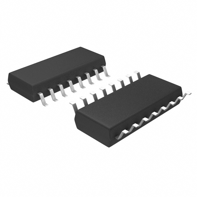
封装信息:
- 16-Lead Small Outline Integrated Circuit (SOIC), JEDEC MS-012, 0.150 Narrow
- 16-Lead Small Outline Package (SOP), EIAJ TYPE II, 5.3mm Wide
- 16-Lead Plastic Dual-In-Line Package (PDIP), JEDEC MS-001, 0.300 Wide