FAN7527BN

FAN7527BN

  • 厂商:

    FAIRCHILD(仙童半导体)

  • 封装:

  • 描述:

    FAN7527BN - Power Factor Correction Controller - Fairchild Semiconductor

  • 详情介绍
  • 数据手册
  • 价格&库存
FAN7527BN 数据手册
www.fairchildsemi.com FAN7527B Power Factor Correction Controller Features • Internal start-up timer • Internal R/C filter eliminates the need for an external R/C filter • Very precise adjustable output over voltage protection • Zero current detector • One quadrant multiplier • Trimmed 1.5% internal band gap reference • Under voltage lockout with 3V of hysteresis • Totem pole output with high state clamp • Low start-up and operating current • 8-Pin DIP or 8-Pin SOP Description The FAN7527B provides simple and high performance active power factor correction. The FAN7527B is optimized for electronic ballasts and low power and high density power supplies which require minimum board size, reduced external components and low power dissipation. Because the R/C filter is included in the current sense block, the external R/C filter is not necessary. Special circuitry has also been added to prevent no load runaway conditions. Regardless of the supply voltage, the output drive clamping circuit limits the overshoot of the power MOSFET gate drive. It greatly enhances the system reliability. 8-DIP Applications • Electronic ballast • SMPS 1 8-SOP 1 Rev 1.0.2 ©2003 Fairchild Semiconductor Corporation FAN7527B Internal Block Diagram Vcc 8 2.5V Ref Vcc + − 11.5V 8.5V UVLO Internal Bias Drive Output Timer R 7 OUT Idet 5 7.2V 2V 1.5V + − Zero Current Detector S Q Static OVP 40k CS 4 8pF + − R Current Sense Comparator Vref Veao(L)=2.25V + − 2.25V 1.8V Vmo MULT 3 Vm1 0 ~ 3.8V Multiplier Vmo K= Vm1 ⋅ (Vm2 − Vref ) − + 0.25V Vm2 Vref~Vref+2.5V Isovp=30uA Idovp=40uA + − Vref Vea(-) 1 INV OVP Current Detector 6 GND 2 EA_OUT Error Amp 2 FAN7527B PIN Description INV 1 2 3 4 (Top View) 8 7 6 5 Vcc OUT GND ldet EA_OUT MULT CS Pin Number 1 2 3 4 5 6 7 8 Pin Name INV EA_OUT MULT CS ldet GND OUT Vcc Pin Function Description Inverting input of the error amplifier. the output of the boost converter should be resistively divided to 2.5V and connected to this pin. The output of the error amplifier. a feedback compensation network is placed between this pin and the INV pin. Input to the multiplier stage. the full-wave rectified ac voltage is divided to less than 2V and is connected to this pin. Input of the PWM comparator. the MOSFET current is sensed by a resistor and the resulting voltage is applied to this pin. an internal R/C filter is included to reject any high frequency noise. Zero current detection input. The ground potential of all the pins. Gate driver output. the push pull output stage is able to drive the power MOSFET with peak current of 500mA. Supply voltage of driver and control circuits. 3 FAN7527B Absolute Maximum Ratings (Ta=25°C) Characteristics Supply voltage Peak drive output current Driver output clamping diodes Vo > Vcc or Vo < -0.3V Detector clamping diodes Error amp, multiplier and comparator input voltages Operating junction temperature Operating temperature range Storage temperature range Power dissipation 8-DIP 8-SOP Symbol VCC IOH,IOL lclamp ldet Vin Tj Topr Tstg Pd Value 30 ±500 ±10 ±10 -0.3 to 6 150 -25 to 125 -65 to 150 1.1 0.8 Unit V mA mA mA V °C °C °C W Thermal Data Characteristics Thermal resistance junction-ambient Max. 8-DIP 8-SOP Symbol Rθja Value 110 150 Unit °C/W Temperature Characteristics (-25°C ≤ Ta ≤ 125°C) Characteristics Temperature stability for reference voltage (Vref) Temperature stability for multiplier gain (K) Symbol ∆Vref ∆K/∆T Min. Typ. 20 -0.2 Max. Unit mV %/°C 4 FAN7527B Electrical Characteristics VCC= 14V, -25°C ≤ Ta ≤ 125°C, unless otherwise stated. Characteristics Start threshold voltage UVLO hysteresis < SUPPLY CURRENT SECTION > Start-up supply current Operating supply current Operating current at OVP Dynamic operating supply current < ERROR AMPLIFIER SECTION > Voltage feedback input threshold Line regulation Temperature stability of Vref (Note1) Input bias current Output source current Output sink current Output upper clamp voltage (Note2) Output lower clamp voltage (Note3) Large signal open loop gain (Note4) Power supply rejection ratio (Note5) Unity gain bandwidth (Note6) Slew rate (Note7) < MULTIPLIER SECTION> Input bias current (pin3) M1 input voltage range (pin3) M2 input voltage range (pin2) Multiplier gain (Note8) Maximum multiplier output voltage Temperature stability of K (Note9) Ib(m) ∆Vm1 ∆Vm2 K ∆K/∆T Vm1 = 1V, Vm2 = 3.5V -25 ≤ Ta ≤ 125°C -0.5 0 Vref 0.36 1.65 0.44 1.8 -0.2 0.5 3.8 Vref+2.5 0.52 1.95 uA V V 1/V V %/°C Vref ∆Vref1 ∆Vref3 Ib(ea) Isource Isink Veao(H) Veao(L) Gv PSRR GBW SR Vm2 = 4V Vm2 = 4V Isource = 0.1mA Isink = 0.1mA 14V ≤ Vcc ≤ 25V Iref = 0mA, Ta = 25°C -25 ≤ Ta ≤ 125°C 14V ≤ Vcc ≤ 25V -25 ≤ Ta ≤ 125°C 2.465 2.44 -0.5 -2 2 60 60 2.5 2.5 0.1 20 -4 4 6 2.25 80 80 1 0.6 2.535 2.56 10 0.5 V V mV mV uA mA mA V V dB dB MHz V/us Ist Icc Icc(ovp) Idcc Vcc = Vth(st) -0.2V Output not switching Vinv = 3V 50kHz, CI = 1nF 10 60 3 1.7 4 100 6 4 8 uA mA mA mA Symbol Vth(st) HY(st) Test Condition Vcc Increasing - Min. 10.5 2 Typ. 11.5 3 Max. 12.5 4 Unit V V < UNDER VOLTAGE LOCKOUT SECTION> Vomax(m) Vinv =0V, Vm1 = 4V 5 FAN7527B Electrical Characteristics (Continued) VCC= 14V, -25°C ≤ Ta ≤ 125°C, unless otherwise stated. Characteristics < CURRENT SENSE SECTION> Input offset voltage (Note8) Input bias current Current sense delay to output (Note11) < ZERO CURRENT DETECT SECTION > Input voltage threshold Detect hysteresis Input low clamp voltage Input high clamp voltage Input bias current < OUTPUT SECTION > Output voltage high Output voltage low Rising time (Note13) Falling time (Note14) Maximum output voltage Output voltage with UVLO activated < RESTART TIMER SECTION> Restart time delay Soft OVP detecting current Dynamic OVP detecting current Static OVP threshold voltage Isovp Idovp Vovp Vinv = 2.7V 25 35 2.1 30 40 2.25 35 45 2.4 uA uA V td(rst) Vm1 = 1V, Vm2 = 3.5V 150 us Voh VoI tr tf Vomax(o) Vomin(o) Io = -10mA Io = 10mA CI = 1nF CI = 1nF Vcc = 20V, Io = 100uA Vcc = 5V , Io = 100uA 10.5 12 11 0.8 130 50 14 1 200 120 16 1 V V ns ns V V Vth(det) HY(det) Vclamp(I) Ib(det) Vclamp(h) Idet = 3mA 1V ≤ Vdet ≤ 5V Vdet increasing Idet = -100uA 1.7 0.2 0.45 6.5 -1 2 0.5 0.75 7.2 -0.1 2.3 0.8 1 7.9 1 ±3 V V V V uA mA Vio(cs) Ib(cs) td(cs) Vm1=0V , Vm2 = 2.2V 0V ≤ Vcs ≤ 1.7V -10 -1 3 -0.1 200 10 1 500 mV uA ns Symbol Test Condition Min. Typ. Max. Unit Input high/low clamp diode current (Note12) Iclamp(d) Note 1 ~ 14: These parameters, although guaranteed, are not 100% tested in production. Pin4_Threshold Multiplier Gain: K = ------------------------------------------------------ ...... ( Vm1 = Vpin3,Vm2 = Vpin2 ) Vm1 × ( Vm2 – Vref ) 6 FAN7527B Typical Performance Characteristics Fig.1 E.A. Output Voltage vs. C.S. Threshold 2.0 Vm1=3.0V Vm1=2.5V Vm1=2.0V Vm1=3.5V Fig.2 Multiplier Input Voltage vs. C.S. Threshold 2.0 1.8 Veao=4.25V Veao=4.0V Veao=3.75V CS Threshold Voltage(V) C.S Threshold Voltage(V) CS Threshold Voltage(V) 1.5 Vm1=4.0V C.S. Threshold Voltage(V) Vm1=1.5V 1.6 1.4 1.2 Veao=4.5V Veao=3.5V Veao=3.25V Vm1=1.0V 1.0 Veao=3.0V 1.0 0.8 Veao=2.75V 0.6 0.4 0.2 Veao=2.5V Vm1=0.5V 0.5 Vm1=0V 0.0 2.0 2.5 3.0 3.5 4.0 4.5 5.0 0.0 0 1 2 3 4 5 EA Output Voltage(V) Multiplier Input Voltage(V) Figure 1. Error Amplifier Output Voltage vs Current Sensing Threshold Fig.3 Supply Current vs. Supply Voltage 0.015 Figure 2. Multiplier Input Voltage vs Current Sensing Threshold Fig.4 Reference Voltage vs. Temperature 2.7 0.012 2.6 0.009 Reference Voltage(V) Supply Current(A) 2.5 0.006 2.4 0.003 0.000 0 10 20 30 40 50 2.3 -25 0 25 50 75 100 125 Supply Voltage(V) Temperature (℃) Figure 3. Supply Current vs Supply Voltage Figure 4. Reference Voltage vs Temperature Fig.5 Start-up Threshold vs. Temperature 14 12 10 8 6 4 2 0 -25 0 25 50 75 100 125 Fig.6 UV Lockout Hysteresis vs. Temperature 5 4 UV Lockout Hyteresis(V) Startup Threshold(V) 3 2 1 0 -25 0 25 50 75 100 125 Temperature (℃) Temperature (℃) Figure 5. Start-Up Threshold vs Temperature Figure 6. UV Lockout Hysteresis vs Temperature 7 FAN7527B Typical Performance Characteristics (Continued) Fig.7 Start-up Supply Current vs. Temperature 100 90 Fig.8 E.A. Source CurrenT vs. Temperature 0 Start-up Supply Current(uA) 80 70 60 50 40 30 20 10 0 -25 0 25 50 75 100 125 -1 EA Source Current(mA) -2 -3 -4 -5 -25 0 25 50 75 100 125 Temperature (℃) Temperature (℃) Figure 7. Start-Up Supply Current vs Temperature Figure 8. Error Amplifier Source Current vs Temperature Fig.10 E.A. Input Bias Current vs. Temperature 0.5 0.4 Fig.9 E.A. Sink Current vs. Temperature 5 EA Input Bias Current(uA) 4 0.3 0.2 0.1 0.0 -0.1 -0.2 -0.3 -0.4 EA Sink Current(mA) 3 2 1 0 -25 0 25 50 75 100 125 -0.5 -25 0 25 50 75 100 125 Temperature (℃) Temperature (℃) Figure 9. Error Amplifier Sink Current vs Temperature Fig.11 Multiplier Gain vs. Temperature 1.0 Figure 10. Error Amplifier Input Bias Current vs Temperature Fig.12 Idet Threshold Voltage vs. Temperature 4.0 0.8 3.2 0.6 Idet Threshold Voltage(V) -25 0 25 50 75 100 125 Multiplier Gain(1/V) 2.4 0.4 1.6 0.2 0.8 0.0 0.0 -25 0 25 50 75 100 125 Temperature (℃) Temperature (℃) Figure 11. Multiplier Gain vs Temperature Figure 12. ldet Threshold Voltage vs Temperature 8 FAN7527B Typical Performance Characteristics (Continued) Fig.13 Idet Input Hysteresis vs. Temperature 1.0 500 450 0.8 Idet Input Hysteresis(mV) 400 350 0.6 Restart Time(us) -25 0 25 50 75 100 125 300 250 200 150 100 50 0.4 0.2 0.0 0 -25 0 25 50 75 100 125 Temperature (℃) Temperature(℃) Figure 13. ldet Input Hysteresis vs Temperature Figure 14. Restart Time vs Temperature Fig.15 Max. Mult. Output Voltage vs. temperature 2.0 Fig.16 Supply Current vs. Temperature 5 Maximum Mult. Output Voltage(V) 1.6 4 Supply Current(mA) 1.2 3 0.8 2 0.4 1 0.0 -25 0 25 50 75 100 125 0 -25 0 25 50 75 100 125 Temperature (℃) Temperature (℃) Figure 15. Max.Mult.Output Voltage vs Temperature Figure 16. Supply Current vs Temperature 9 FAN7527B Mechanical Dimensions Package Dimensions in millimeters 8-DIP 0.018 ±0.004 1.524 ±0.10 0.060 ±0.004 0.46 ±0.10 6.40 ±0.20 0.252 ±0.008 ( #1 #8 9.20 ±0.20 0.362 ±0.008 9.60 MAX 0.378 #4 #5 2.54 0.100 5.08 MAX 0.200 7.62 0.300 3.40 ±0.20 0.134 ±0.008 3.30 ±0.30 0.130 ±0.012 0.33 MIN 0.013 0.79 ) 0.031 0.25 –0.05 0~15° +0.10 0.010 –0.002 +0.004 10 FAN7527B Mechanical Dimensions (Continued) Package Dimensions in millimeters 8-SOP Symbol A A1 A2 B C D E e H h L GP q aaa bbb Min 0.10 1.25 0.35 0.19 4.80 3.80 5.79 0.25 0.50 0 - Nom 0.15 1.45 0.37 0.20 4.90 3.90 1.27BSC 5.99 0.70 0.36 BSC - Max 1.75 0.25 1.50 0.51 0.25 5.00 4.00 6.20 0.50 0.90 8 0.25 0.10 11 FAN7527B Ordering Information Product Number FAN7527BN FAN7527BM Package 8-DIP 8-SOP Operating Temperature -25 ~ +125oC DISCLAIMER FAIRCHILD SEMICONDUCTOR RESERVES THE RIGHT TO MAKE CHANGES WITHOUT FURTHER NOTICE TO ANY PRODUCTS HEREIN TO IMPROVE RELIABILITY, FUNCTION OR DESIGN. FAIRCHILD DOES NOT ASSUME ANY LIABILITY ARISING OUT OF THE APPLICATION OR USE OF ANY PRODUCT OR CIRCUIT DESCRIBED HEREIN; NEITHER DOES IT CONVEY ANY LICENSE UNDER ITS PATENT RIGHTS, NOR THE RIGHTS OF OTHERS. LIFE SUPPORT POLICY FAIRCHILD’S PRODUCTS ARE NOT AUTHORIZED FOR USE AS CRITICAL COMPONENTS IN LIFE SUPPORT DEVICES OR SYSTEMS WITHOUT THE EXPRESS WRITTEN APPROVAL OF THE PRESIDENT OF FAIRCHILD SEMICONDUCTOR CORPORATION. As used herein: 1. Life support devices or systems are devices or systems which, (a) are intended for surgical implant into the body, or (b) support or sustain life, and (c) whose failure to perform when properly used in accordance with instructions for use provided in the labeling, can be reasonably expected to result in a significant injury of the user. www.fairchildsemi.com 8/16/03 0.0m 001 Stock#DSxxxxxxxx  2003 Fairchild Semiconductor Corporation 2. A critical component in any component of a life support device or system whose failure to perform can be reasonably expected to cause the failure of the life support device or system, or to affect its safety or effectiveness.
FAN7527BN
1. 物料型号: - 型号为FAN7527B,由Fairchild Semiconductor生产。

2. 器件简介: - FAN7527B是一款用于功率因数校正(Power Factor Correction, PFC)的控制器,优化用于电子镇流器和低功耗、高密度电源供应器,这些应用要求最小的板卡尺寸、减少外部组件和低功耗。

3. 引脚分配: - 1号引脚(INV):错误放大器的反相输入端,BOOST转换器的输出应分压至2.5V并连接至此引脚。 - 2号引脚(EA OUT):错误放大器的输出端,在此引脚和INV引脚之间放置反馈补偿网络。 - 3号引脚(MULT):乘法器阶段的输入端,全波整流交流电压分压至小于2V并连接至此引脚。 - 4号引脚(CS):PWM比较器的输入端,通过电阻感测MOSFET电流,得到的电压应用于此引脚,内部包含R/C滤波器以排除高频噪声。 - 5号引脚(Idet):零电流检测输入端。 - 6号引脚(GND):所有引脚的地电位。 - 7号引脚(OUT):栅极驱动输出端,推挽输出级能够以500mA的峰值电流驱动功率MOSFET。 - 8号引脚(Vcc):驱动和控制电路的供电电压。

4. 参数特性: - 供电电压:Vcc为30V。 - 峰值驱动输出电流:IOH, IOL为+500mA。 - 驱动输出钳位二极管Vo > Vcc或Vo < -0.3V时的Iclamp为±10mA。 - 检测钳位二极管的Idet为±10mA。 - 错误放大器、乘法器和比较器输入电压Vin为-0.3至6V。 - 工作结温Tj为150°C。 - 工作温度范围Topr为-25至125°C。 - 存储温度范围Tstg为-65至150°C。 - 8-DIP的功耗Pd为1.1W,8-SOP的功耗为0.8W。

5. 功能详解: - FAN7527B提供简单且高性能的主动功率因数校正,优化用于电子镇流器和低功耗、高密度电源供应器,这些应用要求最小的板卡尺寸、减少外部组件和低功耗。由于R/C滤波器包含在电流感测块中,因此不需要外部R/C滤波器。还增加了特殊电路以防止无负载运行条件。无论供电电压如何,输出驱动钳位电路限制了功率MOSFET门驱动的过冲,大大提高了系统的可靠性。

6. 应用信息: - 应用于电子镇流器和SMPS(开关模式电源供应器)。
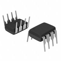
7. 封装信息: - 提供8-Pin DIP和8-Pin SOP两种封装方式。
FAN7527BN 价格&库存

很抱歉,暂时无法提供与“FAN7527BN”相匹配的价格&库存,您可以联系我们找货

免费人工找货