Transient Voltage Suppressor
Formosa MS
SA SERIES
List
List................................................................................................. 1
Package outline............................................................................... 2
Features.......................................................................................... 2
Mechanical data............................................................................... 2
Maximum ratings .............................................................................. 2
Electrical characteristics................................................................... 3~4
Rating and characteristic curves........................................................ 5
Pinning information........................................................................... 6
Taping & bulk specifications for AXIAL devices.................................... 6
Suggested thermal profiles for soldering processes............................. 7
High reliability test capabilities........................................................... 8
http://www.formosams.com/
TEL:886-2-22696661
FAX:886-2-22696141
Page 1
Document ID
Issued Date
Revised Date
DS-222807
2008/02/10
2010/03/10
Revision
B
Page.
8
�Transient Voltage Suppressor
Formosa MS
SA SERIES
500W Axial Leaded Transient Voltage
Suppressors - 5.0V-220V
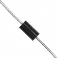
Package outline
Features
DO-15
• Axial lead type devices for through hole design.
• 500W peak pulse power capability with a 10/1000us
waveform, repetition rate (duty cycle): 0.01% .
• Excellent clamping capability.
• Low incremental surge resistance.
• Fast response time from 0V to V , typically less than
1.0(25.4)
MIN.
BR
1 ps for uni-directional & 5 ns for bi-directional types.
• Glass passivated chip junction .
• Lead-free parts meet environmental standards of
MIL-STD-19500 /228
• Suffix "-H" indicates Halogen free parts, ex. SΑ5.0Α-H
.140(3.6)
.104(2.6)
DIA.
.300(7.6)
.230(5.8)
Mechanical data
• Epoxy : UL94-V0 rated flame retardant
• Case : Molded plastic, DO-15
• Lead : Axial leads, solderable per MIL-STD-202,
1.0(25.4)
MIN.
.034(.9)
.028(.7)
DIA.
Method 208 guaranteed
• Polarity: Color band denotes cathode end
• Mounting Position : Any
• Weight : Approximated 0.40 gram
Maximum ratings (AT
Dimensions in inches and (millimeters)
o
T A=25 C unless otherwise noted)
PARAMETER
Symbol
CONDITIONS
SA SERIES
UNIT
W
Peak power dissipation
with a 10/1000us waveform, Note 1 & Fig. 1
P PPM
500
Peak pulse current
with a 10/1000us waveform
I PPM
See table 1
Steady state power dissipation
at T L=75°C lead length 0 . 375” (9 . 5 mm)
P M(AV)
3.0
W
Peak forward surge current
8.3ms single half sine-wave superimposed
on rated load (JEDEC Method), note 2
at 25A for uni-directional types only, note 3
I FSM
70
A
Maximum instantaneours forward voltage
Operating temperature range
Storage temperature range
VF
A
3.5/5.0
V
TJ
-55~+150
O
T STG
-55~+150
O
C
C
O
Note1. Non-repetitive current pulse, per Fig. 3 and derated above T A=25 C per Fig. 2
2. Measured on 8.3 mS single half sine-wave or equivalent square wave, duty cycle=4 pulses per minute maximum
3. V F
很抱歉,暂时无法提供与“SA5.0CA”相匹配的价格&库存,您可以联系我们找货
免费人工找货