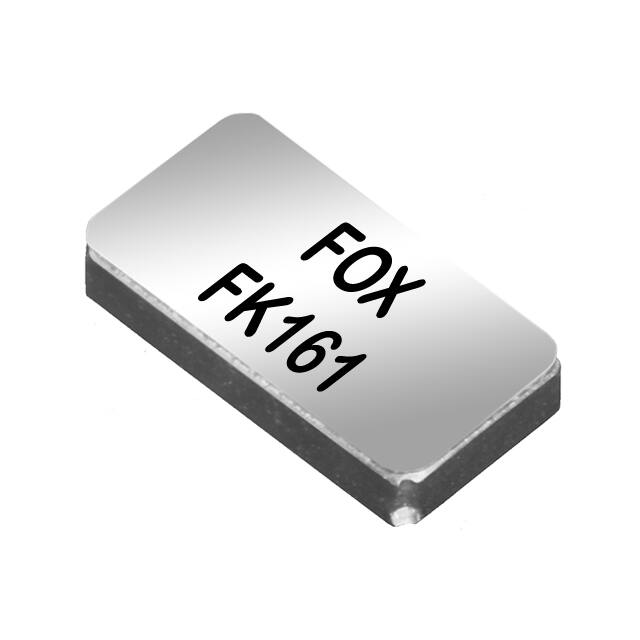
FK161EIWM0.032768-T5 数据手册
FK161
1.6mm x 1.0mm
SMD Tuning Fork
(Former FX161)
STANDARD SPECIFICATIONS
PARAMETERS
Frequency Range
Frequency Tolerance @ 25°C
Frequency Stability, ref 25°C
(Temperature Coefficient)
Temperature Range
Turnover (TO)
Operating (TOPR)
Storage (TSTG)
Equivalent Series Resistance (RS)
Load Capacitance (CL)
Insulation Resistance @ 100VDC
Drive Level
Aging per year (@ 25°C)
Maximum Soldering Temp / Time
Moisture Sensitivity Level (MSL) per
J-STD-033
Termination Finish
Seal Method
Lead (Pb) Free
RoHS Compliant
MAX (Unless otherwise noted)
32.768 kHz
±20PPM
DIMENSIONS / MECHANICAL
SPECIFICATIONS
-0.04 PPM / (∆°C)2
+20°C ~ +30°C
-40°C ~ +85°C
-55°C ~ +125°C
90 kΩ
(See options below)
500MΩ Min
0.5µW (0.1µW Typ)
±3 PPM
260°C / 10 Seconds x2
1
Au over Ni
Seam
Yes
Yes
Temperature Coefficient
-20
°C
-40
-30
-20
-10
0
10
20
30
40
50
60
70
80
0
-40
-60
Note: Dimensional drawing is for reference to critical
specifications defined by size measurements. Certain
non-critical visual attributes, such as side castellations,
etc. may vary.
-80
ppm
-100
-120
-140
-160
-180
Revised A: 11/13/2019
Page 1 of 3
www.foxonline.com
�FK161
1.6mm x 1.0mm
SMD Tuning Fork
(Former FX161)
TAPE SPECIFICATIONS (mm)
A
Ø1.5
B
4.0
C
4.0
D
3.5
E
8.0
F
0.6
REEL SPECIFICATIONS (mm)
REEL QTY
-T5 = 5,000
G
2.0
H
Ø13
I
Ø21
J
Ø60
K
Ø180
L
9.0
M
1.2
Available Options & Part Identification for Tuning Fork Crystal Model K161
Sample PN: FK161EIHM0.032768-T5
F
K161
Fox
Model
Number
E
I
Tolerance
Stability
E = ±20ppm I = -0.04 PPM/
(∆°C)2
H
M
0.032768
-T5
Load
Capacitance
B = 6pF
V = 7pF
W = 9pF
H = 12.5pF
Operating
Temperature
M = -40 ~ +85°C
Frequency
(MHz)
Values Added
Options
Blank = Bulk
T5 = 5,000 pcs
Reliability Test Conditions
Please contact Abracon Quality Assurance department
Revised A: 11/13/2019
Page 2 of 3
www.foxonline.com
�FK161
1.6mm x 1.0mm
SMD Tuning Fork
(Former FX161)
Crystal Unit Handling Precautions
1) Mounting Precautions
• If the board is deformed, such as bending after mounting, peeling of the soldered joint between the
crystal resonator and board may occur producing a crack in the ceramic package, leading to loss of
vacuum, destruction of the internal element, etc. Especially when repaneling the board on which it is
mounted, there is a possibility that a large stress may be applied, please consider board layout and cutting
method to minimize stress on products.
• When the product is automatically mounted on the board, if a large impact is applied to the crystal
resonator, there is a possibility that characteristics may change / deteriorate, or the product may be
broken. When mounting automatically, please set conditions considering the shock to the crystal unit.
Also, please conduct the mounting test beforehand and confirm that there is no influence on the
characteristics to the crystal resonator.
• Cracks may occur in the soldered part by repeated harsh temperature changes for a long time when
mounting due to the board having a expansion coefficient different from that of the ceramics used in the
crystal package. When using under such circumstances, please conduct test beforehand and confirm that
there is no influence on the crystal unit.
• Ceramic packages are small and thin products. So, if/when you rework after mounting, please give
consideration to the selection and handling of the tools to be used.
2) Soldering
Following is typical SMD Pb-free reflow profile for soldering:
Excessive heating time at high temperature may result in deterioration of the characteristics and may
break the crystal unit. For manual rework, heat the lead part at 300℃ or lower for 5 seconds or less.
3) Cleaning
Since a small, thin crystal chip is used for tuning fork crystal units and the frequency approximates that of
an ultrasonic cleaner, the crystal chip may break easily. Therefore, DO NOT perform ultrasonic cleaning.
Revised A: 11/13/2019
Page 3 of 3
www.foxonline.com
�
FK161EIWM0.032768-T5 价格&库存
很抱歉,暂时无法提供与“FK161EIWM0.032768-T5”相匹配的价格&库存,您可以联系我们找货
免费人工找货