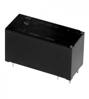
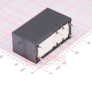
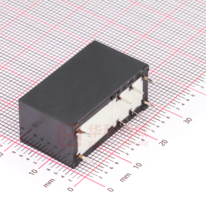
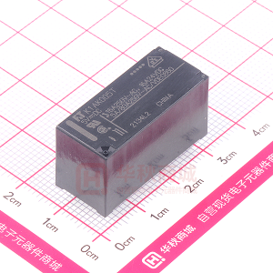
FTR-C1 Series
ULTRA MINIATURE RELAY SIGNAL RELAY FTR-C1 Series
n FEATURES
Dimensions of large contact gap relay Height: 9.3 mm maximum (THT) 9.65 mm maximum (SMT) Length: �5 mm maximum Width: 7.5 mm maximum l Conforms to IEC60950 / EN60950 / UL�950/ C22.2 No.950 spacing & high breakdown voltage Clearance: 2.0 mm ( coil and contacts) Creepage: 2.5 mm ( coil and contacts) l HIGH RELIABILITY Bifurcated contacts l Low power consumption 280 mW (latching type �40mW) l RoHS Compliant since beginning of production
l
RoHS compliant
n ORDERING INFORMATION
[Example] (a) (b) (c) (d) (e) FTR-C� (a)
C A 0�2 G-(B05)* (b) (c) (d) (e) (f) FTR-C1 C: Through hole type G: Surface mount type A: Standard Type B: Single coil latching type Nominal Voltage G: Silver alloy
Series Name Terminal Appearance Operation Function Coil Number Contact Material
Remarks: Actual marking on relay would not carry code FTR and be as below: Ordering code Actual marking FTR-C1CA03G → C1CA03G * If ordering tape and reel package, please add “B05” after the partnumber (tape and reel is only available for SMT type, example: FTR-C�GA003G-B05
�
�FTR-C1 Series
n COIL DATA CHART
Nominal Operating Power (±10%) 280 mW 280 mW 280 mW 280 mW 300 mW Standard type Model THT FTR-C1CA003G FTR-C1CA4.5G FTR-C1CA005G FTR-C1CA012G FTR-C1CA024G SM T FTR-C1GA003G FTR-C1GA4.5G FTR-C1GA005G FTR-C1GA012G FTR-C1GA024G Coil Resistance (±10%) 32.1 Ω 72.3 Ω 89.3 Ω 514 Ω 1920 Ω Must Operate Voltage 2.25 VDC 3.75 VDC 9.00 VDC 18.0 VDC Must Release Voltage 0.3 VDC 0.5 VDC 1.2 VDC 2.4 VDC
Nominal Voltage 3 VDC 4.5 VDC 5 VD C 12VDC 24VDC
3.38 VDC 0.45 VDC
Note: All values in the table are measured at 20˚C. Single coil latching type Model THT FTR-C1CB003G FTR-C1CB4.5G FTR-C1CB005G FTR-C1CB012G FTR-C1CB024G Note: SM T FTR-C1GB003G FTR-C1GB4.5G FTR-C1GB005G FTR-C1GB012G FTR-C1GB024G Nominal Voltage 3 VDC 4.5 VDC 5 VD C 12VDC 24VDC Coil Resistance (±10%) 64 Ω 14 5 Ω 179 Ω 1029 Ω 3200 Ω Set Voltage Reset Voltage Nominal Operating Power (±10%) 140 mW 140 mW 140 mW 140 mW 180 mW
2.25 VDC 2.25 VDC 3.38 VDC 3.38 VDC 3.75 VDC 3.75 VDC 9.00 VDC 9.00 VDC 18.0 VDC 18.0 VDC
- All values in the table are measured at 20˚C. - Single coil latching type is applying to the standard now.
2
�FTR-C1 Series
n SPECIFICATIONS
Item Arrangement Material Contact Resistance (initial) Max. Switching Power Max. Switching Voltage Max. Switching Current Coil Operating Temperature Max. Allowable Voltage Operate Time Release Time (without diode) Resistance (at 500 VDC) Between open contacts Dieelectric Strenght Insulation Surge Strength Mechanical Life Electrical (resistive load) Misoperation Endurance Misoperation Endurance Contact Ratin g Insulation Class IEC060950 UL1950 C22.2 No.950 EN60950 Working Voltage Pollution Degree Clearance Creepage Distance Between adjacent contacts Between coil and contacts Between open contacts Between adjacent contacts Between coil and contacts FTR-C1CA ( )G FTR-C1GA ( )G 2 F o rm C Silver alloy Max. 100m ohm (at 1A 6VDC) 37.5AV / 30W 250VAC, 220 VDC 1A -40˚ C to + 85˚ C (no frost ) 150% nominal voltage (at 20˚ C) Max. 10ms (at nominal voltage, without bounce) Max. 10ms (at nominal voltage, without bounce) Min. 1,000M ohm S 1,500VAC, 1 minut e 1,500VAC, 1 minut e 3,000VAC, 1 minut e 2,500V (at 2/10 microsec ) 2,500V (at 2/10 microsec ) 5,000V (at 2/10 microsec ) 10x106 operations min. (at 10Hz) 100x103 operations min. at 1A, 30VDC, 0.5Hz 100x103 operations min. at 0.1A, 48VDC, 0.5Hz 100x103 operations min. at 0.3A, 125VDC, 0.5Hz 10 to 55 Hz at double amplitude of 3.3 mm 10 to 55 Hz at double amplitude of 5 mm Min. 500 m/s2 Min. 1,000 m/ s2 0.3A 125 VAC 1A 30VDC 0.3 110VDC Supplementary Insulatio n 250 V 2 2.0 mm (between coil and contacts) 2.5 mm (between coil and contacts)
3
Time Value
Vibration Resistance Shock Resistance UL / CSA
�FTR-C1 Series
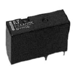
n DIMENSIONS AND SCHEMATICS Through hole type
Polarity Bar
F.T. C�CA003G Japan 003�K
7.4 ±0.�
�4.9 ±0.�
9.1 ± 0.2
(1.1)
5.08 ±0.3 2.54±0.3 2.54±0.3
(1.16)
5.08 ±0.3
n
TERMINAL DESIGNATIONS
Standard type (Bottom view de-energized position)
n
RECOMMENDED MOUNTING PAD
(1.16)
2.54±0.1
+0.1 8-O 0.8 -0.05
(+) 1
3
4
5
3.5
Unit: mm
(-) 12 Polarity Bar
10
9
8 (1.1) 5.08 ±0.1 2.54±0.1
Single Coil Latching type (Bottom view reset position)
(+) (-) 1 SR (+)..(+) 12 Polarity Bar
3
4
5
S shows the polarity of set positin R shows the polarity of reset position
10
9
8
5.08 ±0.1
Unit: mm
4
�FTR-C1 Series
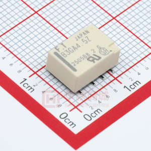
n DIMENSIONS AND SCHEMATICS Surface mount type
Polarity Bar
Japan
0031K
14.9 ± 0.1
7.4 ± 0.1
F.T. C1GA003G
(1.1)
5.08 ±0.3 2.54±0.3
2.54±0.3
3o±2o 5.08 ±0.3 9.4+0.3
9.4 ± 0.25
0.3-0.
Unit: mm
n
TERMINAL DESIGNATIONS
3.16 ±0.1
Standard type (Top view de-energized position)
n
RECOMMENDED MOUNTING PAD
1±0.1 1±0.1 1±0.1
(-) 12
10
9
8
(+) 1 Polarity Bar
3
4
5
Single Coil Latching type (Bottom view reset position)
3.16 ±0.1
5.08 ±0.1 2.54±0.1
2.54±0.1
(-) (+) 12 SR (+) (-) 1 Polarity Bar
10
9
8
S shows the polarity of set positin R shows the polarity of reset position
3
4
7.24±0.1
5
Unit: mm
5
�FTR-C1 Series
n RECOMMENDED SOLDERING CONDITIONS (TEMPERATURE PROFILE)
IRS (Infrared Reflow Soldering)
Note:
Temperature (C)
T3 T2 T1 preheating
soldering
T 3 = 245C max. T 2 = 200C max. cooling T 1 = 165C max.
1.Temperature profiles show the temperature of PC board surface. 2. Please perform soldering test with your actual PC board before mass production, since the temperatures of PC board surfaces vary according to the size of PC board, status of parts mounting and heating method.
0
120 sec maximum
30 sec Max.
n PACKAGING Packaging method (only tape packaging is available) �. Taping standards: JIS C 0806 and RC-�0092B (EIAJ) Orientation 2. Reel type: TB24�6 or TB24�6 Mark side 3. Reel type: RD24D 4. Quantity of � reel: 500 pieces
11.5±0.1 1.75±0.1
Feeding
Tape Dimensions:
0.4
+0.1 O1.5-0
O 2.2
4 ±0.1
17.1
12.5 16±0.1 2±0.1 2±0.5 O 13±0.5 O 21±0.8 25.5+0.1 MAX. 2.0
10.7
Reel Dimensions:
21.05
24±0.3
O 370
Unit: mm
6
�FTR-C1 Series
RoHS Compliance and Lead Free Relay Information
1. General Information
Relays produced after the specific date code that is indicated on each data sheet are lead-free now. Most of our signal and power relays are lead-free. Please refer to Lead-Free Status Info. (http://www.fujitsu.com/us/downloads/MICRO/fcai/relays/lead-free-letter.pdf) l Lead free solder paste currently used in relays is Sn-3.0Ag-0.5Cu. l All signal and most power relays also comply with RoHS. Please refer to individual data sheets. Relays that are RoHS compliant do not contain the 5 hazardous materials that are restricted by RoHS directive (lead, mercury, chromium IV, PBB, PBDE). l It has been verified that using lead-free relays in leaded assembly process will not cause any problems (compatible). l “LF” is marked on each outer and inner carton. (No marking on individual relays). l To avoid leaded relays (for lead-free sample, etc.) please consult with area sales office. l We will ship leaded relays as long as the leaded relay inventory exists. Note: Cadmium was exempted from RoHS on October 2�, 2005. (Amendment to Directive 2002/95/EC)
l
2. Recommended Lead Free Solder Profile
l
Recommended solder paste Sn-3.0Ag-0.5Cu amd Sm-3.0 Cu-Ni (only FTR-B3 and FTR-B4 from February 2005.
Reflow Solder condtion for SMT
Peak Temp.: max. 250°C 250 temperature (°C) 220 Pre-heating Cooling Soldering Pre-heating: Soldering:
Flow Solder condtion:
maximum 120˚C dip within 5 sec. at 260˚C soler bath
Solder by Soldering Iron:
�70 �30
Soldering Iron Temperature: maximum 360˚C Duration: maximum 3 sec.
90~�20 sec. max. �20 sec.
20~30 sec. (duration)
We highly recommend that you confirm your actual solder conditions
3. Moisture Sensitivity
l
Moisture Sensitivity Level standard is not applicable to electromechanical realys. SnAgCu and SnCuNi solder is known as low risk of tin whisker. No considerable length whisker was found by our in-house test.
7
4. Tin Whisker
l
�FTR-C1 Series
Fujitsu Components International Headquarter Offices
Japan Fujitsu Component Limited Gotanda-Chuo Building 3-5, Higashigotanda 2-chome, Shinagawa-ku Tokyo �4�, Japan Tel: (8�-3) 5449-70�0 Fax: (8�-3) 5449-2626 Email: promothq@ft.ed.fujitsu.com Web: www.fcl.fujitsu.com North and South America Fujitsu Components America, Inc. 250 E. Caribbean Drive Sunnyvale, CA 94089 U.S.A. Tel: (�-408) 745-4900 Fax: (�-408) 745-4970 Email: components@us.fujitsu.com Web: http://us.fujitsu.com/components/ Europe Fujitsu Components Europe B.V. Diamantlaan 25 2�32 WV Hoofddorp Netherlands Tel: (3�-23) 55609�0 Fax: (3�-23) 5560950 Email: info@fceu.fujitsu.com Web: http://www.fujitsu.com/emea/services/components/ Asia Pacific Fujitsu Components Asia Ltd. �02E Pasir Panjang Road #04-0� Citilink Warehouse Complex Singapore ��8529 Tel: (65) 6375-8560 Fax: (65) 6273-302� Email: fcal@fcal.fujitsu.com Web: http://www.fujitsu.com/sg/services/micro/components/
©2007 Fujitsu Components America, Inc. All rights reserved. All trademarks or registered trademarks are the property off their respective owners. Fujitsu Components America does not warrant that the content of datasheet is error free. In a continuing effort to improve our products Fujitsu Components America, Inc. reserves the right to change specifications/datasheets without prior notice. Rev. April 13, 2007
8
�
很抱歉,暂时无法提供与“FTR-C1GA003G”相匹配的价格&库存,您可以联系我们找货
免费人工找货- 国内价格
- 1+6.00599
- 30+5.79599
- 100+5.37599
- 500+4.95599
- 1000+4.74599
- 国内价格
- 1+8.3398
- 10+6.9286
- 25+6.1544
- 国内价格
- 1+6.8012
- 10+5.4684
- 30+4.802
- 100+4.1454