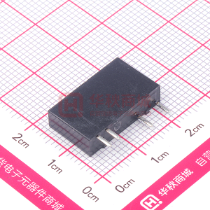
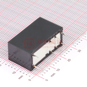
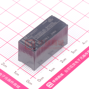
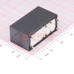
uLtra MINIature Flat High-Frequency relay surface mount, 1GHz-Band, 2 Form C
Ftr-B3-rF series
n Features
l
roHs compliant
l l
l
l l
Excellent high-frequency characteristics up to �GHz (impedance 50 Ohm) by specialized shield structure Surface mount type Space saving, ultra miniature flat package: Height: 6.7mm, Mounting area: 97mm2 Low power consumption: - Standard type: 140mW (230mW at 24V) - Latching type: 100mW (120mW at 24V) High reliable bifurcated contacts RoHS compliant Please see page 6 for more information
n
OrDerING INFOrMatION
FTR-B3 (a) Series Name Terminal Type Operation Function Rated voltage of coil
[Example] (a) (b) (c) (d)
G A 012 Z -RF (b) (c) (d) (e) (f ) FTR-B3 series G: surface mount S: surface mount, space saving version A: standard type B: latching type 1.5 : 1.5 VDC 003 : 3VDC 4.5 : 4.5VDC 006: 6VDC 009 : 9VDC 012: 12 VDC 024 : 24VDC
(e) (f)
Contact material Application category
Z: gold overlay silver alloy RF: high frequency type
Remarks: Actual marking on relay would not carry code FTR and be as below: Ordering code: FTR-B3GA012Z-RF Actual marking: B3GA012Z-RF
�
�Ftr-B3-rF series
n COIL Data CHart
Nominal Coil Resistance Must Operate Voltage (VDC) ( ±�0%) Voltage 1.5 3 4.5 6 9 �2 24 16.1 Ω 64.3 Ω 145 Ω 257 Ω 579 Ω 1,028 Ω 2,504 Ω 1.13 VDC 2.25 VDC 3.38 VDC 4.5 VDC 6.75 VDC 9.0 VDC 18.0 VDC Must Release Voltage 0.15 VDC 0.3 VDC 0.45 VDC 0.6 VDC 0.9 VDC 1.2 VDC 2.4 VDC 230 140 Nominal Power (mW)
Standard type Coil Voltage 1.5 003 4.5 006 009 0�2 024
Latching type (� coil) Coil Voltage 1.5 003 4.5 006 009 0�2 024 * Pulse driven Nominal Coil Resistance Voltage (VDC) ( ±�0%) 1.5 3 4.5 6 9 �2 24 22.5 Ω 90 Ω 203 Ω 360 Ω 810 Ω 1,440 Ω 4,800 Ω Set Voltage 1.13 VDC 2.25 VDC 3.38 VDC 4.5 VDC 6.75 VDC 9.0 VDC 18.0 VDC Reset Voltage -1.13 VDC -2.25 VDC -3.38 VDC -4.5 VDC -6.75 VDC -9.0 VDC -18.0 VDC �20 �00 Nominal Power (mW)
Note: All values in the table valid at 20˚C.
2
�Ftr-B3-rF series
n speCIFICatIONs
Standard Type FTR-B3G( ) ( )Z-RF Contact Arrangement Contact material Contact type Contact resistance (initial value) Contact rating (resistive) Maximum carrying current Maximum switching power Maximum switching voltage Minimum switching current High frequency characteristics Isolation Insertion loss V.S.W.R. Maximum carrying power Maximum switching power Coil Nominal power (at 20°C) Operate power (at 20°C) Operating temperature (no frost) Time value Operate (at nominal voltage) Release (at 0V without diode) Set/Reset pulse Life Vibration resistance Shock resistance Weight Mechanical Electrical Misoperation Endurance Misoperation Endurance 2 Form C (SPDT) Gold overlay silver alloy Bifurcated contact 75mΩ maximum 125 VAC 0.3 A, 30 VDC 1A, 1GHz 1W 2A 62.5 VA / 30W 30 VDC 1A 30dB min. (at 1GHz) 0.2dB max. (at 1GHz) 1.2 max. (at 1GHz) 1W (at 1GHz) 3W (at 1GHz) 0.2 W 0.1W -40°C to +85°C 3ms maximum 3ms maximum �0ms minimum at nominal voltage 50 x �06 operations minimum �00 x �03 operations minimum 10 to 55 Hz at double amplitude of 3.3 mm 10 to 55 Hz at double amplitude of 5.0 mm 750 m/s2 (��±�ms) 1,000 m/s2 (6±1ms) Approximately 1.3 g
*� Minimum switching loads mentioned above are reference values. Please perform the confirmation test with the actual load before production since reference values may vary according to switching frequencies, environmental conditions and expected reliability levels.
n INsuLatION
Item Resistance Dielectric Strength between open contacts between adjacent contacts between coil and contacts FTR-B3-RF Minimum 1,000 MΩ 750 VAC 1 min. 750 VAC 1 min. 750 VAC 1 min. Note at 500 VDC
between metal shield and coil/contacts 500 VAC 1 min.
3
�Ftr-B3-rF series
n DIMeNsIONs
l Dimensions
13.6 11.1
7.7
5.45
0.7
8.2
l Schematics (TOP VIEW)
l Suggested mounting pad (TOP VIEW)
Marking (-)8 7 6 5
2.56
0.8
0.8
0.8 0.8 2.45
0.9
3.2
2.2 2.2 12.35
Unit: mm
2.56
(+)1
2
3
4
2.5
6.64
4
�Ftr-B3-rF series
n reFereNCe Data - High Frequency Characteristics
Sample relay: Coil nominal voltage 12V type Measuring condition: Impedance 50 Ohm
5
�Ftr-B3-rF series
roHs Compliance and Lead Free relay Information
1. General Information
Relays produced after the specific date code that is indicated on each data sheet are lead-free now. All of our signal and power relays are lead-free. Please refer to Lead-Free Status Info. (http://www.fujitsu.com/us/downloads/MICRO/fcai/relays/lead-free-letter.pdf) l Lead free solder paste currently used in relays is Sn-3.0Ag-0.5Cu. From February 2005 forward Sn-3.0CU-Ni will be used for the FTR-B3 and FTR-B4 series relays. l All signal and power relays also comply with RoHS. Please refer to individual data sheets. Relays that are RoHS compliant do not contain the 5 hazardous materials that are restricted by RoHS directive (lead, mercury, chromium IV, PBB, PBDE). l It has been verified that using lead-free relays in leaded assembly process will not cause any problems (compatible). l “LF” is marked on each outer and inner carton. (No marking on individual relays). l To avoid leaded relays (for lead-free sample, etc.) please consult with area sales office. l We will ship leaded relays as long as the leaded relay inventory exists. Note: Cadmium was exempted from RoHS on October 21, 2005. (Amendment to Directive 2002/95/EC)
l
2. Recommended Lead Free Solder Profile
l
Recommended solder paste Sn-3.0Ag-0.5Cu and Sn-3.0Cu-Ni (only FTR-B3 and FTR-B4 from February 2005.
Reflow Solder condition
Peak Temp.: max. 250°C 250 temperature (°C) 220 Pre-heating Cooling Soldering
Flow Solder condition:
Pre-heating: Soldering:
maximum 120˚C dip within 5 sec. at 260˚C solder bath
Solder by Soldering Iron:
170 130
Soldering Iron Temperature: maximum 360˚C Duration: maximum 3 sec.
90~120 sec. max. 120 sec.
20~30 sec. (duration)
We highly recommend that you confirm your actual solder conditions
3. Moisture sensitivity
l
Moisture Sensitivity Level 3 for FTR-B3 relays. SnAgCu and SnCuNi solder is known as low risk of tin whisker. No considerable whisker length was found by our in-house test.
6
4. tin Whisker
l
�Ftr-B3-rF series
Fujitsu Components International Headquarter Offices
Japan Fujitsu Component Limited Gotanda-Chuo Building 3-5, Higashigotanda 2-chome, Shinagawa-ku Tokyo 141, Japan Tel: (81-3) 5449-7010 Fax: (81-3) 5449-2626 Email: promothq@ft.ed.fujitsu.com Web: www.fcl.fujitsu.com North and south america Fujitsu Components America, Inc. 250 E. Caribbean Drive Sunnyvale, CA 94089 U.S.A. Tel: (1-408) 745-4900 Fax: (1-408) 745-4970 Email: components@us.fujitsu.com Web: http://us.fujitsu.com/printers/ europe Fujitsu Components Europe B.V. Diamantlaan 25 2132 WV Hoofddorp Netherlands Tel: (31-23) 5560910 Fax: (31-23) 5560950 Email: info@fceu.fujitsu.com Web: emea.fujitsu.com/components/ Asia Pacific Fujitsu Components Asia Ltd. �02E Pasir Panjang Road #01-01 Citilink Warehouse Complex Singapore 118529 Tel: (65) 6375-8560 Fax: (65) 6273-3021 Email: fcal@fcal.fujitsu.com Web: http://www.fujitsu.com/sg/services/micro/components/
©2008 Fujitsu Components America, Inc. All rights reserved. All trademarks or registered trademarks are the property of their respective owners. Fujitsu Components America or its affiliates do not warrant that the content of datasheet is error free. In a continuing effort to improve our products Fujitsu Components America, Inc. or its affiliates reserve the right to change specifications/datasheets without prior notice. Rev. November 3, 2008.
7
�
很抱歉,暂时无法提供与“FTR-B3GB024Z-RF”相匹配的价格&库存,您可以联系我们找货
免费人工找货- 国内价格
- 1+7.828
- 10+6.46
- 25+5.7095
- 国内价格
- 1+6.00599
- 30+5.79599
- 100+5.37599
- 500+4.95599
- 1000+4.74599
- 国内价格
- 1+3.52
- 10+3.245
- 30+3.19
- 100+3.025


 工商网监
湘ICP备2023018690号
工商网监
湘ICP备2023018690号