FTR-K1 SERIES
POWER RELAY
ULTRA SMALL HIGH VOLTAGE DC RELAY
FTR-J2 Series
FEATURES
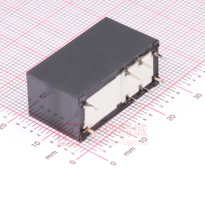
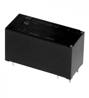
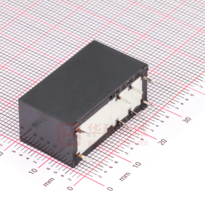
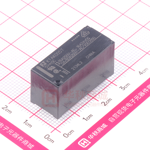
10A, 450VDC high-voltage switching (2 x 10A, 200VDC switching) Contact voltage drop: typical 0.1V Inrush current 150A (capacitive load) Compact size (LxWXH= 24x23.5x27mm) 2 x 1 form A Coil sensitivity 1W (each coil connect in series) High insulation between contacts and coil - Insulation distance : Clearance/creepage > 6mm - Dielectric strength : 4,000 VAC - Surge strength : 10,000 V (1.2 x 50μsec) Plastic materials conform to UL94 flame class V-0 Flux proof, RTII RoHS compliant Please see page 8 for more information
PARTNUMBER INFORMATION
[Example] FTR-J2 A (a) (b) K (c) 012 (d) W (e)
(a) (b) (c) (d) (e)
Relay type Contact configuration Coil power Coil rated voltage Contact material
FTR-J2 : FTR-J2 Series A K 012 W : 2 x 1 form A : Standard sensitivity : 5....110VDC Coil rating table at page 3 : Silver alloy
Actual marking does not carry the type name : "FTR" E.g.: Ordering code: FTR-J2AK012W Actual marking: J2AK012W
1
�FTR-K1 SERIES FTR-J2 SERIES
SPECIFICATION
Item Contact Data Configuration Material Contact resistant (initial) Contact rating FTR-J2 2 x 1 form A Silver alloy Max. 100 mOhm at 1A, 6VDC 10A, 450VDC (resistive load) (+ polarity pin 7 and 4) * each NO contact connected in series 10A, 200VDC (resistive load) (single contact) + (polarity pin 7 and 4) * for each NO contact 10A, 500VDC (resistive load), 50 operations * each NO contact connected in series 10A, 250VDC (resistive load) * for each NO contact 12A Peak 150A 600VDC, each NO contact connection in series 300VDC, each NO contact Typical 0.1V (at nominal contact current) 2M operations 10K operations Maximum 70% of nominal voltage Minimum 5% of nominal voltage -40 to +85 °C Max. 15ms (without bounce) Max. 5ms (no diode) Min. 1000MOhm at 500VDC Between open contacts 1,000VAC (50/60Hz) 1min Dielectric strength Surge strength Other Vibration resistance Shock Weight Sealing Between ontact sets Between contacts and coil Coil to contacts Misoperation Endurance Misoperation Endurance 4,000VAC (50/60Hz) 1min 1,000 VAC (50/60 Hz) 1 min. 10,000V/ 1.2 x 50μs standard wave 10 to 55Hz double amplitude 1.5mm 10 to 55Hz double amplitude 1.5mm Min. 200m/s² (11 ± 1ms) Min. 1,000m/s² (6 ± 1ms) Approximately 26g Flux proof RTII
Overload switching * Maximum carrying current Inrush current Maximum switching voltage Contact voltage drop (initial) Life Coil Data Mechanical Electrical Operate voltage (at 20 °C) Release voltage (at 20 °C) Operating temperature range (no frost) Timing Data Insulation Operate (at nominal voltage) Release (at nominal voltage) Resistance (initial)
Note: Use a varistor as a protective circuit against reverse surge connected parallel to the coil. The reverse blocking voltage should be about 3 times the value of the power source voltage. * Minimum switching loads mentioned above are reference values. Please perform the confirmation test with actual load before production since reference values may vary according to switching frequencies, environmental contions and expected reliability levels.
2
�FTR-K1 SERIES FTR-J2 SERIES
COIL RATING
Standard single coil Coil Code 005 006 012 024 048 060 110 Rated Coil Coil Resistance Voltage +/- 10% (Ohm) * (VDC) 5 6 12 24 48 60 110 47 68 270 1,100 4,400 6,790 22,800 Must Operate Voltage (VDC) * 3.5 4.2 8.4 16.8 33.6 42 77 Must Release Voltage (VDC) * 0.25 0.3 0.6 1.2 2.4 3 5.5 Approximately 0.53 Rated Power (W) (±10%)
2 coils in series (Connect relay coil terminal No.2 to No.3) See note 2. Coil Code 005 006 012 024 048 060 110 Rated Coil Coil Resistance Voltage +/- 10% (Ohm) * (VDC) 10 12 24 48 96 120 220 94 136 540 2,200 8,800 13,580 45,600 Must Operate Voltage (VDC) * 7 8.4 16.8 33.6 67.2 84 154 Must Release Voltage (VDC) * 0.5 0.6 1.2 2.4 4.8 6 11 Approximately 1.06 Rated Power (W) (±10%)
2 coils in parallel (Connect relay coil terminal No.1 to No.3 and No.2 to No.4) Coil Code 005 006 012 024 048 060 110 Rated Coil Coil Resistance Voltage +/- 10% (Ohm) * (VDC) 5 6 12 24 48 60 110 23.5 34 135 550 2,200 3,395 11,400 Must Operate Voltage (VDC) * 3.5 4.2 8.4 16.8 33.6 42 77 Must Release Voltage (VDC) * 0.25 0.3 0.6 1.2 2.4 3 5.5 Approximately 1.06 Rated Power (W) (±10%)
Note 1: All values in the tables are valid for 20°C and zero contact current. Note 2: Nominal voltage is different from indication of part number. Please refer to the coil rating chart "single coil (10A, 200VDC configuration)" for single coil configuration data. Note 3: Please use with nominal voltage. When energizing higher voltage to coil, please refer to characteristic data "coil temperature rise" and "operating range" (page 4) to set suitable voltage. * Specified operate values are valid for pulse wave voltage.
3
�FTR-K1 SERIES FTR-J2 SERIES
SAFETY STANDARDS
Type UL Compliance UL 508 Contact rating 10A, 450VDC, resistive, 10,000 cycles for series connection of each NO contact 10A, 400VDC, resistive, 10,000 cycles for series connection of each NO contact 10A, 200VDC, resistive, 10,000 cycles for each NO contact 10A, 400VDC, resistive, 10,000 cycles for series connection of each NO contact 10A, 200VDC, resistive, 10,000 cycles for each NO contact
VDE
0435
CHARACTERISTIC DATA
* Each NO contact connect in series
* Each NO contact
4
�FTR-K1 SERIES FTR-J2 SERIES
SCHEMATICS
DIMENSIONS
PC BOARD PATTERN
Bottom view
Unit: mm
5
�FTR-K1 SERIES FTR-J2 SERIES
CIRCUIT
Load circuit and input circuit (coil sides) for 10A, 450VDC 2 coils connect in series
(Varistor) (Note 2)
BOTTOM VIEW
Load circuit contact terminals have polarities (+) and (-). Coils do not have polarity.
Load circuit and input circuit (coil sides) for 10A, 450VDC 2 coils connect in parallel
(Varistor) (Note 3)
BOTTOM VIEW
Note 1: In case 2 coils are connected in series, connect coil terminal #2 to #3 on PCB circuit. In case 2 coils are connected in parallel, connect coil terminal #1 to #3 and connect coil terminal #2 to #4 on PCB. Regarding terminal number, refer to schematics data. Note 2: Please use varistor as surge protection device. If varistor will not be used, the electrical life need to be derated. Note 3: Varistor surge protection device should be connect parallel to coil(s). Suitable voltage of varistor is 3 times the coil voltage. Note 4: For max. contact life and correct functioning of the relay, positive polarity of load should be connected to pin 8 and pin 5. If not, damage to the relay can occur. Warning: At current loads at max. switching capacity 10A (450VDC) correct polarity is vital for the correct and safe functioning of the relay.
6
�FTR-K1 SERIES FTR-J2 SERIES
CIRCUIT
Load circuit and input circuit (coil sides) for 10A, 200VDC (dual circuits) 2 coils connect in series
(Varistor) (Note 1)
BOTTOM VIEW
Load circuit contact terminals have polarities (+) and (-). Coils have no polarity.
Load circuit and input circuit (coil sides) for 10A, 200VDC (dual circuits)
(Varistor) (Note 3)
BOTTOM VIEW
Note 1: In case 2 coils are connected in series, connect coil terminal #2 to #3 on PCB circuit. In case 2 coils are connected in parallel, connect coil terminal #1 to #3 and connect coil terminal #2 to #4 on PCB. Regarding terminal number, refer to schematics data. Note 2: Please use varistor as surge protection device. If varistor will not be used, the electrical life need to be derated. Note 3: Varistor surge protection device should be connect parallel to coil(s). Suitable voltage of varistor is 3 times the coil voltage. Note 4: For max. contact life and correct functioning of the relay, positive polarity of load should be connected to pin 8 and pin 5. If not, damage to the relay can occur. Warning: At current loads at max. switching capacity 10A (200VDC) correct polarity is vital for the correct and safe functioning of the relay.
7
�FTR-K1 SERIES FTR-J2 SERIES
RoHS Compliance and Lead Free Information
1. General Information
All signal and power relays produced by Fujitsu Components are compliant with RoHS directive 2002/95EC including amendments. Cadmium as used in electrical contacts is exempted from the RoHS directives on October 21st, 2005. (Amendment to Directive 2002/95/EC) All of our signal and power relays are lead-free. Please refer to Lead-Free Status Info for older date codes at: http://www.fujitsu.com/us/downloads/MICRO/fcai/relays/lead-free-letter.pdf Lead free solder plating on relay terminals is Sn-3.0Ag-0.5Cu, unless otherwise specified. This material has been verified to be compatible with PbSn assembly process.
2. Recommended Lead Free Solder Profile
Recommended solder Sn-3.0Ag-0.5Cu.
Flow Solder condition:
Pre-heating: Soldering: maximum 120˚C dip within 5 sec. at 260˚C solder bath
Solder by Soldering Iron:
Soldering Iron Temperature: maximum 360˚C Duration: maximum 3 sec.
We highly recommend that you confirm your actual solder conditions
3. Moisture Sensitivity
Moisture Sensitivity Level standard is not applicable to electromechanical relays, unless otherwise indicated.
4. Tin Whiskers
Dipped SnAgCu solder is known as presenting a low risk to tin whisker development. No considerable length whisker was found by our in house test.
8
�FFTR-K1SERIES TR-J2 SERIES
Fujitsu Components International Headquarter Offices
Japan Fujitsu Component Limited Gotanda-Chuo Building 3-5, Higashigotanda 2-chome, Shinagawa-ku Tokyo 141, Japan Tel: (81-3) 5449-7010 Fax: (81-3) 5449-2626 Email: promothq@ft.ed.fujitsu.com Web: www.fcl.fujitsu.com North and South America Fujitsu Components America, Inc. 250 E. Caribbean Drive Sunnyvale, CA 94089 U.S.A. Tel: (1-408) 745-4900 Fax: (1-408) 745-4970 Email: components@us.fujitsu.com Web: http://us.fujitsu.com/components Europe Fujitsu Components Europe B.V. Diamantlaan 25 2132 WV Hoofddorp Netherlands Tel: (31-23) 5560910 Fax: (31-23) 5560950 Email: info@fceu.fujitsu.com Web: emea.fujitsu.com/components/ Asia Pacific Fujitsu Components Asia Ltd. 102E Pasir Panjang Road #01-01 Citilink Warehouse Complex Singapore 118529 Tel: (65) 6375-8560 Fax: (65) 6273-3021 Email: fcal@fcal.fujitsu.com Web: http://www.fujitsu.com/sg/services/micro/components/
©2010 Fujitsu Components Europe B.V. All rights reserved. All trademarks or registered trademarks are the property of their respective owners. The contents, data and information in this datasheet are provided by Fujitsu Component Ltd. as a service only to its user and only for general information purposes. The use of the contents, data and information provided in this datasheet is at the users’ own risk. Fujitsu has assembled this datasheet with care and will endeavor to keep the contents, data and information correct, accurate, comprehensive, complete and up to date. Fujitsu Components Europe B.V. and affiliated companies do however not accept any responsibility or liability on their behalf, nor on behalf of its employees, for any loss or damage, direct, indirect or consequential, with respect to this datasheet, its contents, data, and information and related graphics and the correctness, reliability, accuracy, comprehensiveness, usefulness, availability and completeness thereof. Nor do Fujitsu Components Europe B.V. and affiliated companies accept on their behalf, nor on behalf of its employees, any responsibility or liability for any representation or warrant of any kind, express or implied, including warranties of any kind for merchantability or fitness for particular use, with respect to these datasheets, its contents, data, information and related graphics and the correctness, reliability, accuracy, comprehensiveness, usefulness, availability and completeness thereof. Rev. November 23, 2010
9
�