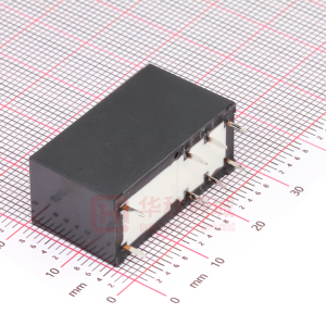
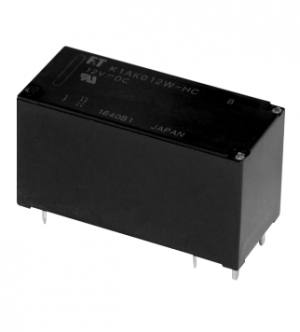
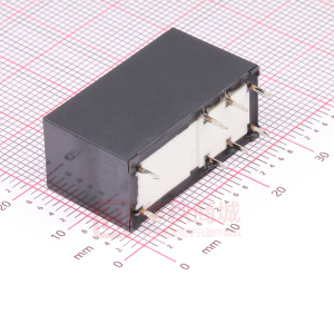
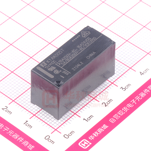
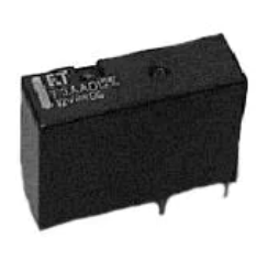
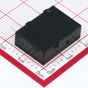
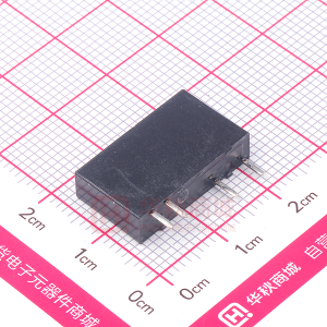
FTR-K3 SERIES
POWER RELAY
1 POLE - 20A Heavy Load RoHS compliant FTR-K3 Series
SPST 20A and #250 tab terminal type is also available l Low coil power (780mW) l Cadmium free contacts l SAFETY STANDARDS UL, CSA, VDE,CQC approved l RoHS Compliant since production
l
n FEATURES
n ORDERING INFORMATION
[Example]
(a) (b) (c) (d) (e) (f)
FTR-K3 J B 0�2 W – ( ) (a) (b) (c) (d) (e) (f )
FTR-K3 : FTR-K3 Series A J B 005 0�8 W : � form A (SPST-NO) (PCB terminal) : � form A (SPST-NO) (Tab terminal) : Standard (780 mW) : 5 VDC, : �8 VDC : Silver alloy : 006 : 6VDC, 024: 24VDC, 009 : 9VDC 048 : 48VDC 0�2 : �2VDC
Series Name Contact Arrangement Coil Type / Enclosure Nominal Voltage Contact Material / TV type Special Designation
Actual marking does not carry the type name : "FTR" E.g.: Ordering code: FTR-K3AB0�2W Actual marking: K3AB0�2W
�
�FTR-K3 SERIES
n PART NUMBERS
400mW type Ordering Part Number FTR-K3AB005W FTR-K3AB006W FTR-K3AB009W FTR-K3AB0�2W FTR-K3AB0�8W FTR-K3AB024W FTR-K3AB048W FTR-K3JB005W FTR-K3JB006W FTR-K3JB009W FTR-K3JB0�2W FTR-K3JB0�8W FTR-K3JB024W FTR-K3JB048W J: � form A Tab terminal FTR-K3 B: 780 mW A: � form A PCB terminal Series Contact Coil Power Coil Voltage 5 6 9 �2 �8 24 48 5 6 9 �2 �8 24 48 W: Silver alloy Contact Material
n COIL DATA CHART
Coil Voltage 005 006 009 0�2 0�8 024 048 Nominal Voltage (VDC) 5 6 9 �2 �8 24 48 Coil Must Operate Must Resistance Voltage*2 Release Voltage*2 (±�0%) 32 Ω 46 Ω 105 Ω 185 Ω 415 Ω 740 Ω 2,955 Ω 3.5 VDC 4.2 VDC 6.3 VDC 8.4 VDC �2.6 VDC �6.8 VDC 33.6 VDC 0.5 VDC 0.6 VDC 0.9 VDC �.2 VDC �.8 VDC 2.4 VDC 4.8 VDC 780 Nominal Power (mW)
Note: All values in the table are measured at 20°C. *�: No contact current at 20°C *2: Specified values are subject to pulse wave voltage
2
�FTR-K3 SERIES
n SPECIFICATIONS
Item Contact Arrangement Material Configuration Resistance (initial) Rating Maximum Carrying Current*� Maximum Switching Current Maximum Switching Rating Maximum Switching Voltage Maximum Switching Load*2 Coil Nominal Power (at 20ºC) Operate Power (at 20ºC) Operating Temperature Time Value Life Operate (without diode) Release (without diode) Mechanical Electrical Resistive Motor Inverter Other Vibration Resistance Shock Resistance Weight Misoperation Endurance Misoperation Endurance FTR-K3 � form A Silver alloy Single Maximum 100 mΩ at 1 A, 6 VDC 20 A, 250 VAC (resistive) 25A 25A 6,250VA 250 VAC �00 mA 5VDC 780mW 380 mW -40ºC to +60ºC (no frost) Maximum 20ms (at nominal voltage, no bounce) Maximum �0ms (at nominal voltage, no bounce) 20 x �06 operations minimum �00 x �03 operations min. 200 x �03 operations min. 30 x �03 operations min. �0 to 55 Hz, at double amplitude of 0.7 mm �0-55Hz, at double amplitude of �.5 mm Min. �00m/s2 (��±�ms) Approximately 25g Min. �,000m/s2 (6±�ms)
*� Need to consider the head from PCB when max. current is more than �0A.
*2 Minimum switching loads mentioned above are reference values. Please perform the confirmation test with the actual load before production since reference values may vary according to switching frequencies, environmental conditions and expected reliability levels.
3
�FTR-K3 SERIES
n INSULATION
Item Resistance (initial) Dielectric Strength open contacts coil and contacts FTR-K� Minimum 1,000 MΩ 1 min. �,000 VAC (50/60 Hz) � min. 5,000 VAC (50/60 Hz) � min. 8,500 V �.2 x 50µs standard wave Note at 500 VDC
Surge Voltage (coil and contact)
n SAFETY STANDARDS
Type UL Compliance UL 508 E636�4 CSA C22.2 No. �4 LR 40304 Contact rating FTR-K3 Flammability: UL 94-V0 (plastics) 20A, 277 VAC (resistive) � HP, �25VAC 2 HP, 277VAC, �00,000 ops.
VDE CQC
0435 0400�009�79
Complies with NEMKO, DEMKO, FIMKO
n CHARACTERISTIC DATA
100
Nominal voltage multiplying factor
ing
Coil Temperature Rise
2.2 2.0 1.8 1.6 1.4 1.2 1.0 0.8 0.6 0 25A
Operating Range
0A
Temperature Rise (deg.)
80 25A
20A
60
40
20 0A 0 0.2 0.4 0.6 0.8 1.0 1.2
m
era ust op
te volt
age (h
ot coil
)
0.8
1.0
1.2
0
p must o
erate v
oltage
(cool c
oil)
20
40
60
80
100
er (W)
Coil Power (W)
Ambient temperature (ºC)
4
�FTR-K3 SERIES
Maximum Switching Power Life Curve
AC250 V resistive 50 30 20 10 5 3 2 1 AC250 V COSØ=0.4 AC250 V COSØ=0.7
100
Switching Current (A)
50 20 10 5 2 1 AC resistive
0.5 0.2 0.1 10
Contact Voltage (V)
20
50
100
200
500 1000
Service Life (104 operations)
100
0
Contact Current Load (A)
100
5
10
15
20
25
100 90
Distribution of Operation & Release Voltage Distribution (%)
FTR-K3JB012W n=200 Operate Release
100 90 80 70 60 50 40 30 20 10
Distribution of Operation & Release Time
Release
Distribution of Contact Resistance
FTR-K3JB012W n=200
Distribution (%)
70 60 50 40 30 20 10 0 0 10 20 30 40
50
Distribution (%)
8 9 10 11 12
80
FTR-K3JB012W n=200 Operate
90 80 70 60 50 40 30 20 10
60
70
80
90 100
0
0
1
2
3
4
Nominal Voltage Multiplying Factor
Voltage (V) Contact resistance (mΩ) Voltage (V)
�0 8
_ _
Time (ms)
5
6
7
0
Contact Resistance (mΩ)
10
0
5
10
15 20
25
30
35
40
45
50
Mechanical Test
Operate
_ _ _
10 8 6 4 2
_
Electrical Test
Voltage (V)
Operate
_ _
Electrical Test
Operate
_ _ _
8 6 4 2 0 50 20 10 5 2 1 0.5
_ _
×
_
6 4 2 0 50 20 �0 5
○
_
○
_
○
_
_
○
○
_
○
_
_
○
○
_
○
_
○
_
○
_
_ _
Contact resistance (mΩ)
×
_
× _
Release
_
_
_ _
_ _
×
Release
_ _
_
×
× _
Release
Contact resistance (mΩ)
× _
× _
× _
_
_
×
× _
× _
_ _
× ×
_
×
0 50 20 10 5
_ _
×
_
×
FTR-K3JB012W n 10
_
×
_
×
_ _
×
_ × _
_
_
_
2 � 0.5
FTR-K3JB0�2W n=�0
2 1 0.5
FTR-K3JB012W n 10
_
×
_
_
_
_
0.33Hz Duty 50% AC250V, 20A (resistive)
0.33Hz Duty 50% AC250V, 80A cosφ 0.7 0.3sec 20A cosφ 0.9
Initial 20
Operation (x�04) Electrical Test
_
60
�00
200
Initial
Operation (x104)
5
10
Initial
10
20
Operation (x104)
Voltage (V)
10 8 6 4 2 0 20 10 5 2
○
_
Operate
_
○
_
_ _
Contact resistance (mΩ)
×
Release
_ _
×
_
×
_
×
_
_
1 0.5
FTR-K3JB012W n6
0.13Hz Duty 38% AC100V, 200A 20A
Initial
Operation (x104)
3
5
�FTR-K3 SERIES
n DIMENSIONS
l Dimensions FTR-K3 JB
l Schematics (BOTTOM VIEW)
30.1+0.3 (10.45) 12.8
#250
15.7+0.3 6.35 IN 7.95 10.4
23.3+0.3
l PC board mounting hole layout (BOTTOM VIEW)
27.6 (1.25) 6.25
0.5
0.8 1.5
0.8 1.5
1.5
0.3
4-φ 1.8
12 22 (5.05)
l Dimensions FTR-K3 AB
30.1+0.3 15.7+0.3
l Schematics (BOTTOM VIEW)
IN 23.3 +0.3
0.5
0.8 1.5
0.8 1.5
1.5
0.3
l PC board mounting hole layout (BOTTOM VIEW)
27.6 (1.25) 6.25 4-φ 1.8 12 22 (5.05) 5.75
5.75
Unit: mm
6
�FTR-K3 SERIES
RoHS Compliance and Lead Free Relay Information
1. General Information
Relays produced after the specific date code that is indicated on each data sheet are lead-free now. All of our signal and power relays are lead-free. Please refer to Lead-Free Status Info. (http://www.fujitsu.com/us/downloads/MICRO/fcai/relays/lead-free-letter.pdf) l Lead free solder paste currently used in relays is Sn-3.0Ag-0.5Cu. l All signal and power relays also comply with RoHS. Please refer to individual data sheets. Relays that are RoHS compliant do not contain the 5 hazardous materials that are restricted by RoHS directive (lead, mercury, chromium IV, PBB, PBDE). l It has been verified that using lead-free relays in leaded assembly process will not cause any problems (compatible). l “LF” is marked on each outer and inner carton. (No marking on individual relays). l To avoid leaded relays (for lead-free sample, etc.) please consult with area sales office. l We will ship leaded relays as long as the leaded relay inventory exists. Note: Cadmium was exempted from RoHS on October 2�, 2005. (Amendment to Directive 2002/95/EC)
l
2. Recommended Lead Free Solder Profile
l
Recommended solder paste Sn-3.0Ag-0.5Cu.
Reflow Solder condition Flow Solder condition:
Pre-heating: Soldering: maximum 120˚C dip within 5 sec. at 260˚C soler bath
Solder by Soldering Iron:
Soldering Iron Temperature: maximum 360˚C Duration: maximum 3 sec.
We highly recommend that you confirm your actual solder conditions
3. Moisture Sensitivity
l
Moisture Sensitivity Level standard is not applicable to electromechanical realys. Dipped SnAgCu solder is known as low risk tin whisker. No considerable length whisker was found by our in house test.
4. Tin Whisker
l
7
�FTR-K3 SERIES
Fujitsu Components International Headquarter Offices
Japan Fujitsu Component Limited Gotanda-Chuo Building 3-5, Higashigotanda 2-chome, Shinagawa-ku Tokyo �4�, Japan Tel: (8�-3) 5449-70�0 Fax: (8�-3) 5449-2626 Email: promothq@ft.ed.fujitsu.com Web: www.fcl.fujitsu.com North and South America Fujitsu Components America, Inc. 250 E. Caribbean Drive Sunnyvale, CA 94089 U.S.A. Tel: (�-408) 745-4900 Fax: (�-408) 745-4970 Email: components@us.fujitsu.com Web: http://www.fujitsu.com/us/services/edevices/components/ Europe Fujitsu Components Europe B.V. Diamantlaan 25 2�32 WV Hoofddorp Netherlands Tel: (3�-23) 55609�0 Fax: (3�-23) 5560950 Email: info@fceu.fujitsu.com Web: emea.fujitsu.com/components/ Asia Pacific Fujitsu Components Asia Ltd. 102E Pasir Panjang Road #0�-0� Citilink Warehouse Complex Singapore ��8529 Tel: (65) 6375-8560 Fax: (65) 6273-302� Email: fcal@fcal.fujitsu.com Web: http://www.fujitsu.com/sg/services/micro/components/
©2010 Fujitsu Components America, Inc. All rights reserved. All trademarks or registered trademarks are the property of their respective owners. Fujitsu Components America or its affiliates do not warrant that the content of datasheet is error free. In a continuing effort to improve our products Fujitsu Components America, Inc. or its affiliates reserve the right to change specifications/datasheets without prior notice. Rev. April �6, 20�0.
8
�
很抱歉,暂时无法提供与“FTR-K3”相匹配的价格&库存,您可以联系我们找货
免费人工找货- 国内价格
- 1+6.00599
- 30+5.79599
- 100+5.37599
- 500+4.95599
- 1000+4.74599
- 国内价格
- 1+8.3398
- 10+6.9286
- 25+6.1544
- 国内价格
- 1+5.8016
- 10+4.6942
- 30+4.1454
- 100+3.5966