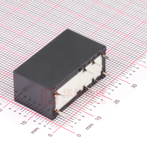
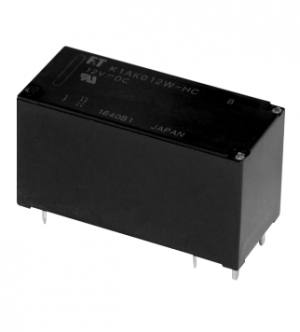
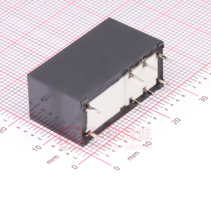
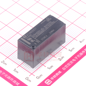
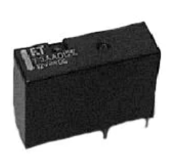
QUIET POWER RELAY
1 POLE—20 A
(FOR AUTOMOTIVE APPLICATIONS)
FTR-P1 SERIES
s FEATURES
Original construction, where reduction of operational noise is considered when mounted on PCB, made it possible to design this quiet relay. (Average acoustic noise level: 53 dB, distance 10 cm) q New types of materials are used for the conductive parts, allowing this compact relay to carry 20 AMP. q Two types of contact material are available for various contact loads. q Wider contact gap (0.6 mm) version is also available for enhanced cut-off ability to overload condition.
q
s ORDERING INFORMATION
[Example]
(a) (b) (c)
(d)
(e) (f)
Note: Part No. is printed on the top of relay as follows. (Example) Designation ordered: FTR-P1CN012W1 Stamp: P1CN012W1
NO TF OR DE NE SIG W N
FTR-P1 (a) C (b) N 012 W1 (c) (d) (e) -** (f )
Series Name FTR-P1: FTR-P1 Relay C Contact Arrangement : 1 form C (SPDT) Contact Gap N P : 0.3 mm gap : 0.6 mm gap : 9 VDC : 10 VDC : 12 VDC Nominal Voltage 009 010 012 W1 Contact Material : Silver-tin oxide-indium Custom Designation To be assigned for custom specification
1
�FTR-P1 SERIES (QUIET TYPE)
s SPECIFICATIONS
Item Contact Arrangement Material Voltage Drop (resistance) Ratings Maximum Carrying Current Maximum Inrush Current (reference) Max. Switching Current (reference) Min. Switching Load*1 1 form C (SPDT) Silver-tin oxide-indium (W1 type) Maximum 100 mV (at 2 A 12 VDC) 14 VDC/20 A (locked motor load) 14 VDC/inrush 20 A, break 4 A (motor free load) 20 A/ 1 hour (25°C, 100% rated coil voltage) W1 Type: 60 A 30 A at 16 VDC 6 VDC 1 A Specifications
Coil
Time Value
Life
Other
*1
Values when switching a resistive load at normal room temperature and humidity, and in a clean environment. The minimum applicable load varies with the switching frequency and operating environment.
s COIL DATA CHART
q 0.3 mm contact gap type MODEL
NO TF OR DE NE SIG W N
(reference) Operating Temperature Range –40°C to +85°C (no frost) (reter to the CHARACTERISTIC DATA) Storage Temperature Range –40°C to +100°C (no frost) Operate (at nominal voltage) Maximum 10 ms Release (at nominal voltage) Maximum 5 ms Mechanical Electrical 1 ×10⁷ operations minimum 2 ×10⁵ operations minimum (locked motor load) 4 ×10⁵ operations minimum (motor free load) Vibration Resistance Shock Resistance Weight 10 to 55 Hz (double amplitude of 1.5 mm) Misoperation Endurance 100 m/s2 1,000 m/s 2 Approximately 10.0 g W1 TYPE FTR-P1CN009W1 FTR-P1CN010W1 FTR-P1CN012W1 Nominal voltage 9 VDC 10 VDC 12 VDC Coil resistance (±10%) 135 Ω 180 Ω 240 Ω Must operate voltage 5.4 V (at 20°C) 6.8 V (at 85°C) 6.3 V (at 20°C) 7.9 V (at 85°C) 7.3 V (at 20°C) 9.2 V (at 85°C) Must release voltage 0.7 V 0.8 V 0.9 V 73°C/W Thermal resistance
2
�FTR-P1 SERIES (QUIET TYPE)
q 0.6 mm Contact Gap Type MODEL W1 TYPE FTR-P1CP009W1 FTR-P1CP010W1 FTR-P1CP012W1 Nominal voltage 9 VDC 10 VDC 12 VDC Coil resistance (±10%) 100 Ω 135 Ω 180 Ω Must operate voltage 5.4 V (at 20°C) 6.8 V (at 85°C) 6.3 V (at 20°C) 7.9 V (at 85°C) 7.3 V (at 20°C) 9.2 V (at 85°C) Must release voltage 0.7 V 0.8 V 0.9 V 65°C/W Thermal resistance
Note: Values in the table of coil resistance and must release voltage are measured at 20°C.
s SUITABLE APPLICATION
CONTACT MATERIAL W1: Silver-tin oxide-indium
s CHARACTERISTIC DATA
1. MAXIMUM BREAK CAPACITY
Contact switching current (A)
Number of operations (x104)
NO TF OR DE NE SIG W N
SUITABLE LOAD Door lock Power window Solenoids, etc. (locked rotor)
2. LIFE
50 40 35 30 25 20
14 VDC Motor locked load
30
20 10 5
Resistive load 0.3 mm gap
Locked motor load 0.3 mm gap 15 0.6 mm gap
0.6 mm gap
12 10
10
10 15 20 25 30 35 40 50 Voltage between contacts (V)
15 20 25 30 35 404550 Locked motor current (A)
3
�FTR-P1 SERIES (QUIET TYPE)
3. LIFE TEST (EXAMPLE)
• Test item 14 V DC-20 A Motor Lock 200,000 operations minimum • Test circuit
RL-1 N.O. N.C. N.O. N.C. RL-2 M
• Shift of pick-up drop-out voltage
100
Percent of rated coil voltage (%)
80 60
PICK-UP
40
DROP-OUT
20 0
• Current wave form
(RL-1) 20 A 0A (RL-2) 20 A 0A 20 sec
0.3 sec
Percent of rated coil voltage (%)
• Test item 14 V DC-20 A motor free 400,000 operations minimum • Test circuit
NO TF OR DE NE SIG W N
Initial
1
10
100
• Shift of contact resistance
1000
Contact Resistance (mΩ)
(Measured at 6 V-1 A)
100
Break Make
10
10 sec
0.3 sec
Initial
1
10 Number of operations (x104)
100
• Shift of pick-up drop-out voltage
100 80
60 40 20 0
PICK-UP
N.O. N.C.
DROP-OUT
M
Initial
1
10
100
• Shift of contact resistance • Current wave form
20 A 4A 0A 16 A
Contact Resistance (mΩ)
1000
Break Make
(Measured at 6 V-1 A)
100
10
Initial
1
10 Number of operations (x104)
100
4
�4. COIL TEMPERATURE RISE
120 100 80 60 40 20 0
6. VIBRATION RESISTANCE CHARACTERISTICS
(m/s ) 100
Acceleration
7. SHOCK RESISTANCE CHARACTERISTICS
� � � � � �
(V) 15
FTR-P1 SERIES (QUIET TYPE)
5. OPERATING COIL VOLTAGE RANGE (EXAMPLE)
Coil temperature rise (°C)
Applied voltage to the coil
(2) carrying current : applied coil power 10 A 0.8 W 0.6 W
10
CONTINUOUSLY APPLICABLE COIL VOLTAGE RANGE
2
NO TF OR DE NE SIG W N
at 20˚C
0.8 W 0.6 W (1) carrying current : applied coil power 0 A
5
–30 0 50 100 Operating temperature (˚C)
0
10 20 30 Applied time (minutes)
Dual amplitude (mm) 0.5 0.1
5
1
0.01
50
44 m/s
2
Automotive electronic standard
Frequency : 10~2000 Hz Acceleration : 100 m/s2 maximum Vibration direction : see diagram Detection level : chatter of 100 µs minimum
10
Range where chattering occurs N.O. contact coil not energized on Z-direction Z 1000 2000
FTR-P1 Y
X
10
50
100
500
Frequency (Hz)
(m/s2) 1,000
Shock level
800 600 400 200 0
Shock application time : 11 ms, half-sine wave Test material : coil, energized and de-energized Shock direction: see diagram Detection level : chatter of 100 µs minimum Y2 Z2 FTR-P1 Z1 X2 X1
Y1
X1
X2
Y1
Y2
Z1
Z2
Shock direction
: N.C. contact (coil de-energized) : N.C. contact (coil energized)
5
�FTR-P1 SERIES (QUIET TYPE)
s REFERENCE DATA
Distribution of operate and release voltage
80 FTR-P1 n = 100 60
Operate Release
100 80
Distribution of operate and release time
FTR-P1 n = 100 Operate Release
Distribution of contact resistance
100 80 FTR-P1 n = 100
Distribution (%)
60 40 20 0
Distribution (%)
8
Distribution (%)
60 40 20 0
40
20
0
0 10 20 30 40 50 60 70 80 Nominal voltage multiplying factor (%)
s DIMENSIONS
q Dimensions
NO TF OR DE NE SIG W N
0 1 2 345 Time (ms) 6 7
0
10 20 30 40 50 60 70 80 Contact resistance (mΩ)
P1CP012W1
F&T
9616
21.8+0.2
16.9+0.6
3.5
16.3+0.2
(2.3)
(2.45)
12.0
q Mounting hole layout (BOTTOM VIEW)
q Schematic (BOTTOM VIEW) N.C. 4 5 1 COM
12.0
5-¿ 1.2 12.2 Tolerance –0.1 2.1
3 N.O.
2
Unit : mm
6
�FTR-P1 SERIES (QUIET TYPE)
Fujitsu Components International Headquarter Offices
Japan Fujitsu Component Limited Gotanda-Chuo Building 3-5, Higashigotanda 2-chome, Shinagawa-ku Tokyo 141, Japan Tel: (81-3) 5449-7010 Fax: (81-3) 5449-2626 Email: promothq@ft.ed.fujitsu.com Web: www.fcl.fujitsu.com North and South America Fujitsu Components America, Inc. 250 E. Caribbean Drive Sunnyvale, CA 94089 U.S.A. Tel: (1-408) 745-4900 Fax: (1-408) 745-4970 Email: marcom@fcai.fujitsu.com Web: www.fcai.fujitsu.com
Europe Fujitsu Components Europe B.V. Diamantlaan 25 2132 WV Hoofddorp Netherlands Tel: (31-23) 5560910 Fax: (31-23) 5560950 Email: info@fceu.fujitsu.com Web: www.fceu.fujitsu.com Asia Pacific Fujitsu Components Asia Ltd. 102E Pasir Panjang Road #04-01 Citilink Warehouse Complex Singapore 118529 Tel: (65) 6375-8560 Fax: (65) 6273-3021 Email: fcal@fcal.fujitsu.com www.fcal.fujitsu.com
© 2005 Fujitsu Components America, Inc. All company and product names are trademarks or registered trademarks of their respective owners. Rev.06/07/2005
NO TF OR DE NE SIG W N
7
�
很抱歉,暂时无法提供与“FTR-P1CN010W1”相匹配的价格&库存,您可以联系我们找货
免费人工找货- 国内价格
- 1+6.00599
- 30+5.79599
- 100+5.37599
- 500+4.95599
- 1000+4.74599
- 国内价格
- 1+8.3398
- 10+6.9286
- 25+6.1544
- 国内价格
- 1+6.0368
- 10+4.8216
- 30+4.2238
- 100+3.626