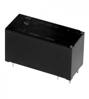
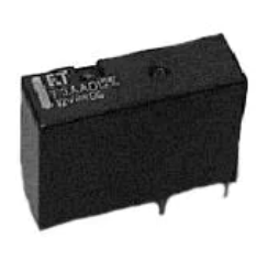
FTR-P3 SERIES
COMPACT POWER RELAY
1 POLE—25 A FOR AUTOMOTIVE APPLICATIONS
FTR-P3 Series
Compact for high density packaging. (65% volume of previous generation FBR 5�/52 Series). l High contact capacity with proven contact material. (100,000 operations, 14 V, 25 A achieved, even with reduced size). l 125˚C version is available. l Surface mount compatible version (reflowable) is available. l Coil power savings (600mW nominal achieved with state-of-the-art magnetic analysis/ design). l Ease of PCB layout (all terminals on perimeter, coil and contact terminals separated). l Optional over-voltage circuit breaking capability (0.6mm gap, contact our representative). l Packaging for auto-insertion (tube packing, 30 relays/tube).
l l
RoHS compliant
n FEATURES
RoHS compliant since date code: 0630 Please see page 8 for more information
n ORDERING INFORMATION
[Example]
(a) (b) (c) (d) (e) (f)
FTR-P3 C N 0�2 W� *** (a) (b) (c) (d) (e) (f)
FTR-P3 Series C N P 009 0�0 0�2 W� : � Form C : 0.3mm gap : 0.6mm gap : 09VDC : �0VDC : �2VDC
Series Name Contact Arrangement Contact Gap Nominal Coil Voltage Contact Material Custom Designation
: Silver-tin oxide-indium
Nil : Standard (85˚C) -01 : High temperature (125˚C) -05 : High temperature (125˚C) and reflowable -06 : High temperature (125˚C) and reflowable Higher stand-off
Note: The part number stamped on the relay cover does not include "FTR". Example: Ordering part number: FTR-P3CN0�2W� Stamped on part number: P3CN0�2W�
n
TYPICAL APPLICATIONS
Power seat Wiper/IWW Tilt steering Retractable antenna
Power window Door lock Sun roof
�
�FTR-P3 SERIES
n SPECIFICATIONS
Specification Item Arrangement Material Contact path Voltage Drop (Initial) Contact Rating Maximum Carry Current*1 Maximum Switching Current (Reference) Minimum Switching Load*2 (Reference) Coil Operating Ambient Temperature Range Storage Temperature Range Operate (at nominal voltage) Release (at nominal voltage) Mechanical Life Electrical Vibration Resistance Shock Resistance Operational Operational Withstand, no damage Standard 1 form C (SPDT ) Silver-tin oxide-indiu m Maximum 100 mV (at 1 A 12 VDC) 25 A at 14VDC (locked motor load) 25 A / 1hour (25° C, 100% rated coil voltage) 35 A at 16 VD C 1 A, 6 VD C -40° C to +85° C (no frost ) -40° C to +125° C (no frost ) High temperature version (-01, -05, -06)
-40° C to+100° C (no frost ) -40° C to +125° C (no frost ) Maximum 10ms (not including bounce) Maximum 5ms (not including bounce, no diode) Maximum 15ms (not including bounce, with diode) 10 x 1 06 operations minimum 100 x 103 operations minimum, 14 VDC, 25 A (locked motor load) (1 operation = 1 forward and 1 reverse) 10-55Hz, 1.5mm double amplitude (=9.13G @ 55Hz) 100 m/ s2 minimum (10G) 1, 000 m/ s2 minimum (100G) 100M ohms @500 VA C 500 VA C Approximately 5 g
Timing Values
Other
Insulation Resistance (initial) Dielectric Withstanding Voltage (initial) Weight
*1 Need to consider the head from PCB when max. current is more than 10A. *2 Values when switching a resistive load at normal room temperature and humidity and in a clean environment. The minimum switching load varies with the switching frequency and operating environment.
2
�FTR-P3 SERIES
n COIL DATA CHART
FTR-P3 Series (0.25mm contact gap)
Model
Nominal Coil Voltage 9VD C 10VD C 12VD C
Coil Resistance (±10% at 20ºC) 13 5 Ω 16 7 Ω 24 0 Ω
Must Operate Voltage 5.5VDC (at 20° C) 6.9VDC (at 85° C) 6.3VDC (at 20° C) 7.9VDC (at 85° C) 7.3VDC (at 20° C) 9.2VDC (at 85° C)
Must Release Voltage (at 20ºC) 0.75VDC 0.9VDC 1.0VDC
Coil Power at Nominal Voltage 0.6 W 0.6 W 0.6 W
Thermal Resistance (approx.) 73° C/ W 73° C/ W 73° C/ W
FTR-P3CN009W1 ( ) FTR-P3CN010W1 ( ) FTR-P3CN012W1 ( )
Note: ( ) is "Nil", "-0�", "05", or "-06" FTR-P3 Series (0.6mm contact gap)
Model
Nominal Coil Voltage 9VDC �0VDC �2VDC
Coil Resistance (±�0% at 20°C) 100Ω 125Ω 167Ω
Must Operate Voltage 5.5VDC (at 20ºC) 6.9VDC (at 85ºC) 6.3VDC (at 20ºC) 7.9VDC (at 85ºC) 7.3VDC (at 20ºC) 9.2VDC (at 85ºC)
Must Release Voltage (at 20°C) 0.75VDC 0.9VDC �.0VDC
Coil Thermal Power at Resistance Nominal (approx.) Voltage 0.8W 0.8W 0.8W 73ºC/W 73ºC/W 73ºC/W
FTR-P3-CP009W� FTR-P3-CP0�0W� FTR-P3-CP0�2W�
n REFERENCE DATA
100
Operating/release voltage distribution
Data: FTR-P3 Units: n = 100
Operate Release
100
Operate and release time distribution
Data: FTR-P3 Units: n = 100 Operate Release with diode
100
Contact resistance distribution
Data: FTR-P3 Units: n = 100
80
80
80
Distribution (%)
Distribution (%)
Distribution (%)
0 0.5 1 1.5 2 2.5 3 3.5 4 4.5 5 5.5 6 6.5 7
60
60
60
40
40
40
20
20
20 0
0
0
10
20 30 40 50 60 Ratio to rated voltage (%)
70
80
0
Time (ms)
0
10
20
30
40
50
60
70
80
Contact resistance (m)
3
�FTR-P3 SERIES
n CHARACTERISTIC DATA 1. LIFE TEST (EXAMPLES)
Percent of nominal coil voltage (%)
• Change of operate and release voltage • Test item �� V DC-25 A 100 locked motor �00K operations* minimim 80 0.25 seconds ON, 9.75 seconds OFF OPERATE
RL-1 N.O. N.C. N.O. N.C. RL-2 M
60 40 20
RELEASE
20 50 100 500 1000
0
• Current wave form
(RL-1) 25 A 0A (RL-2) 25 A 0A 0.25 sec 10 sec
• Change in contact resistance
1000
Initial
Number of operations* (x 103 times) (Measured at 6 VDC, 1A wet)
Contact Resistance (mΩ)
100
0.25 sec 5 sec
10
* 1 operation = 1 forward and 1 reverse
1 20 50
Initial
Number of operations* (x 103 times)
100
500
1000
RL N.O. N.C. M
Percent of nominal coil voltage (%)
• Test item • Change of operate and release voltage �� V DC, 100 inrush current: �7A motor free 80 300K operations minimum 0.25 seconds ON, OPERATE 9.75 seconds OFF 60
40 20 0
RELEASE Initial
20 50
Number of operations (x 103 times)
100
500
1000
• Current wave form
17 A
• Change in contact resistance
1000
(Measured at 6 VDC, 1A wet)
Contact Resistance (mΩ)
0A
1.5 A 12 A
100
10
1
Initial
20
50
Number of operations (x 103 times)
100
500
1000
�
�FTR-P3 SERIES
2. MAXIMUM BREAK CAPACITY
100
3. COIL TEMPERATURE RISE
Coil temperature rise (degrees C)
120 100 80 60 40 20 0
0.6 W 0.6 W
50
Motor lock load FTR-P3CN P3CP P3CN
Ambient temperature: 20C
Switching current (A)
Contact carry current: 20A
0.6 W
20
10
Contact carry current: 10A Contact carry current: 0.0A
5
2
1 10 12 14 16 20 25 30
0
10
20
30
Applied time (minutes)
Source voltage (VDC)
4. OPERATING COIL VOLTAGE RANGE
Ratio of coil voltage to nominal voltage (%)
140
120
Continuous operating range at 10A carry current
100
80
60
ate -oper Must
-20 0 20 40
volta
ge
40 -40 60 80 100
Ambient temperature C
5
�FTR-P3 SERIES
5. VIBRATION RESISTANCE CHARACTERISTIC
Dual amplitude (mm)
Acceleration (m/s2)
100 50 44 m/s2
5
1
0.5
0.1
0.01
On-vehicle Electronic equipment Standard 10 10 50 100 Frequency (Hz) 500
Frequency : 10~2000 Hz Acceleration : 100 m/s2 maximum Vibration axis : see drawing below Detection level : generation of 1 ms or longer contact opening Range where chattering occurs Break contact Coil deenergized on X-axis
Z
FTR-P3 Y X
1000
2000
6. SHOCK RESISTANCE CHARACTERISTIC
1,000 800 600 Shock duration : 111 ms, half-sine wave Test condition: coil, energized and de-energized Impact direction: see drawing below Detection level : generation of 1ms or longer contact opening Y2 : Break contact (coil de-energized) : Make contact (coil energized) X1 X2 Y1 Y2 Impact direction Z1 Z2 Z2 FTR-P3 Z1 X1 X2
Shock level (m/s2)
Y1
400 200 0
6
�FTR-P3 SERIES
n DIMENSIONS AND SCHEMATICS
Dimensions (Nil, -0� and -05) 17.4 +0.5 -0.5 7.2 -0.5
+0.5
13.5+0.5 -0.5 3.5 +0.5 -0.5 0.4 +0.5 -0.5
5 +0.2 5 +0.2 5 +0.2 -0.2 -0.2 -0.2
1.2 +0.2 -0.2
0.85
5.5 +0.2 -0.2
PCB mounting hole layout and schematic (Bottom view) 0.32 -0.10
+0.15
2.5 0
+0.1 5 -0.1 5
+1.3
Soldering
0.4 +0.15 -0.10
0.8 +0.15 -0.10
1
+0.15 -0.10
1.2
+0.1 -0.1
+0.1 -0.1
5
+0.1 -0.1
0.8 +0.15 -0.10
5.5 +0.1 -0.1
¿1.5 0
+0.1
0.8 +0.15 -0.10
0.2
+0.15 -0.10
1
+0.15 -0.10
0.4 +0.15 -0.10
Dimensions (-06)
5
5
5
(1.2)
5- φ 1. 5 ±
0 .1
0
5. 5
Units: mm
7
�FTR-P3 SERIES
RoHS Compliance and Lead Free Relay Information
1. General Information
Relays produced after the specific date code that is indicated on each data sheet are lead-free now. Most of our signal and power relays are lead-free. Please refer to Lead-Free Status Info. (http://www.fujitsu.com/us/downloads/MICRO/fcai/relays/lead-free-letter.pdf) l Lead free solder paste currently used in relays is Sn-3.0Ag-0.5Cu. l All signal and most power relays also comply with RoHS. Please refer to individual data sheets. Relays that are RoHS compliant do not contain the 5 hazardous materials that are restricted by RoHS directive (lead, mercury, chromium IV, PBB, PBDE). l It has been verified that using lead-free relays in leaded assembly process will not cause any problems (compatible). l “LF” is marked on each outer and inner carton. (No marking on individual relays). l To avoid leaded relays (for lead-free sample, etc.) please consult with area sales office. l We will ship leaded relays as long as the leaded relay inventory exists. Note: Cadmium was exempted from RoHS on October 21, 2005. (Amendment to Directive 2002/95/EC)
l
2. Recommended Lead Free Solder Profile
l
Recommended solder paste Sn-3.0Ag-0.5Cu.
Reflow Solder condition Flow Solder condition:
Pre-heating: Soldering: maximum 120˚C dip within 5 sec. at 260˚C solder bath
Solder by Soldering Iron:
Soldering Iron Temperature: maximum 360˚C Duration: maximum 3 sec.
We highly recommend that you confirm your actual solder conditions
3. Moisture Sensitivity
l
Moisture Sensitivity Level standard is not applicable to electromechanical realys. Dipped SnAgCu solder is known as low risk tin whisker. No considerable length whisker was found by our in house test.
4. Tin Whisker
l
8
�FTR-P3 SERIES
Fujitsu Components International Headquarter Offices
Japan Fujitsu Component Limited Gotanda-Chuo Building 3-5, Higashigotanda 2-chome, Shinagawa-ku Tokyo ��� 8630, Japan Tel: (8�-3) 5��9-70�0 Fax: (8�-3) 5��9-2626 Email: promothq@fcl.fujitsu.com Web: www.fcl.fujitsu.com North and South America Fujitsu Components America, Inc. 250 E. Caribbean Drive Sunnyvale, CA 9�089 U.S.A. Tel: (�-�08) 7�5-�900 Fax: (�-�08) 7�5-�970 Email: components@us.fujitsu.com Web: http://www.fujitsu.com/us/services/edevices/components/ Europe Fujitsu Components Europe B.V. Diamantlaan 25 2�32 WV Hoofddorp Netherlands Tel: (3�-23) 55609�0 Fax: (3�-23) 5560950 Email: info@fceu.fujitsu.com Web: emea.fujitsu.com/components/ Asia Pacific Fujitsu Components Asia Ltd. 102E Pasir Panjang Road #0�-0� Citilink Warehouse Complex Singapore ��8529 Tel: (65) 6375-8560 Fax: (65) 6273-302� Email: fcal@fcal.fujitsu.com Web: http://www.fujitsu.com/sg/services/micro/components/
©2009 Fujitsu Components America, Inc. All rights reserved. All trademarks or registered trademarks are the property of their respective owners. Fujitsu Components America or its affiliates do not warrant that the content of datasheet is error free. In a continuing effort to improve our products Fujitsu Components America, Inc. or its affiliates reserve the right to change specifications/datasheets without prior notice. Rev. March �, 2009.
9
�
很抱歉,暂时无法提供与“FTR-P3”相匹配的价格&库存,您可以联系我们找货
免费人工找货- 国内价格
- 1+6.00599
- 30+5.79599
- 100+5.37599
- 500+4.95599
- 1000+4.74599
- 国内价格
- 1+8.3398
- 10+6.9286
- 25+6.1544
- 国内价格
- 1+6.1152
- 10+4.9
- 30+4.3022
- 100+3.7044