FUJITSU(富士通)
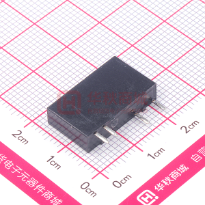
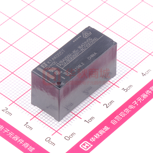
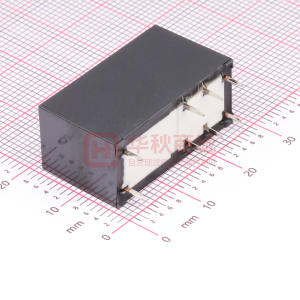
FTR-P5 - SILENT RELAY FOR AUTOMOTIVE APPLICATIONS 1 POLE-25 A - Fujitsu Component Limited.
很抱歉,暂时无法提供与“FTR-P5”相匹配的价格&库存,您可以联系我们找货
免费人工找货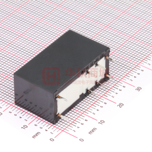
库存:0
库存:42
库存:0

库存:0

库存:0
库存:164
关注我们的微信

下载发烧友APP

电子发烧友观察

版权所有 © 湖南华秋数字科技有限公司
电子发烧友(电路图)湘公网安备 43011202000918 号电信与信息服务业务经营许可证:合字B2-20210191 工商网监
湘ICP备2023018690号
工商网监
湘ICP备2023018690号