TClamp3302N
Low Capacitance TVS
for Ethernet and Telecom Interfaces
PROTECTION PRODUCTS - TransClampΤΜ
Description
Features
Transient protection for high-speed data lines to
A TransClampΤΜ is a low capacitance TVS array designed
to protect high speed data interfaces. This series has
been specifically designed to protect sensitive components which are connected to data and transmission
lines from overvoltage caused by ESD (electrostatic
discharge), CDE (Cable Discharge Events), and Lightning.
These devices integrate low capacitance, surge-rated
compensation diodes with a high power transient
voltage suppressor (TVS). The compensation diodes
are arranged in a bridge pattern allowing the device to
be connected in common mode and/or differential
mode. This allows the designer maximum flexibility and
reduces parts count. The capacitance of the device is
limited to 12pF maximum from line-to-line to ensure
correct signal transmission on high-speed lines.
These devices may be used to meet Telcordia GR-1089CORE short-haul (intra-building) surge requirements and
will withstand a minimum 100 A surge for a 2/10µs
pulse.
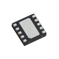
The TClampTM3302N is in a 10-pin, RoHS/WEEE compliant, SLP2626P10 package. It measures 2.6 x 2.6 x
0.60mm. The leads are spaced at a pitch of 0.5mm
and are finished with lead-free NiPdAu. They are
particularly well suited for applications where board
space is at a premium such as integrated connectors/
magnetics and carrier class Ethernet equipment.
Bellcore 1089 (Intra-Building) 100A (2/10µs)
IEC 61000-4-2 (ESD) ±15kV (air), ±8kV (contact)
IEC 61000-4-4 (EFT) 40A (5/50ns)
IEC 61000-4-5 (Lightning) L5, 95A (8/20µs)
Low capacitance (12pF line-to-line)
Low operating voltages (3.3V)
Low clamping voltage
Small SLP Package saves board space
Solid-state technology
Mechanical Characteristics
SLP2626P10 10L package
RoHS/WEEE Compliant
Nominal Dimensions: 2.6 x 2.6 x 0.60 mm
Lead Pitch: 0.5mm
Molding compound flammability rating: UL 94V-0
Marking: Marking Code
Packaging: Tape and Reel
Applications
Circuit Diagram
10/100/1000 Ethernet
T3/E3
Integrated Magnetics
Carrier Class Equipment
Customer Premise Equipment
Package Configuration
2.60
1 2
LINE 1
CL
(1, 2, 3)
CL 2.60
Center Tab
0.50 BSC
0.60
LINE 2
(8, 9, 10)
10 Pin SLP package (Bottom Side View)
Nominal Dimensions in mm
Revision 01/17/2008
1
www.semtech.com
�TClamp3302N
PROTECTION PRODUCTS
Absolute Maximum Rating
Rating
Symbol
Value
Units
Peak Pulse Power (tp = 2/10µs)
Ppk
2500
Watts
Peak Pulse Current (tp = 2/10µs)
IPP
120
A
Peak Pulse Current (tp = 8/20µs)
IPP
95
A
ESD per IEC 61000-4-2 (Air)
ESD per IEC 61000-4-2 (Contact)
VESD
30
30
kV
TJ
-40 to +85
°C
TSTG
-55 to +150
°C
Operating Temperature
Storage Temperature
Electrical Characteristics (T=25oC unless otherwise specified)
TClamp3302N
Parameter
Symbol
Conditions
VRWM
T=25°C to 85°C
Punch-Through Voltage
VPT
IPT = 2µA
T=25°C
3.5
V
Snap-Back Voltage
VSB
ISB = 50mA
2.8
V
Reverse Leakage Current
IR
VRWM = 3.3V, T=25°C
1
µA
Clamping Voltage
VC
IPP = 100A, tp = 2/10µs
Line-to-Ground
22
V
Clamping Voltage
VC
IPP = 100A, tp = 2/10µs
Line-to-Line
25
V
Junction Capacitance
Cj
Between I/O pins and
Gn d
VR = 0V, f = 1MHz
25
pF
Between I/O pins
VR = 0V, f = 1MHz
12
pF
Reverse Stand-Of f Voltage
2008 Semtech Corp.
2
Minimum
Typical
Maximum
Units
3.3
V
www.semtech.com
�TClamp3302N
PROTECTION PRODUCTS
Typical Characteristics
Non-Repetitive Peak Pulse Power vs. Pulse Time
Power Derating Curve
100
110
% of Rated Power or IPP
Peak Pulse Power - PPP (kW)
100
10
1
90
80
70
60
50
40
30
20
10
0
0.1
0.1
1
10
100
0
1000
25
Normalized Junction Capacitance
vs. Reverse Voltage (Line-to-Line)
75
100
125
150
Normalized Junction Capacitance
vs. Reverse Voltage (Line-to-Ground)
1.5
1.5
f = 1 MHz
1.4
1.4
1.3
CJ (VR) / CJ (VR=0)
1.3
CJ (VR) / CJ (VR=0)
50
Ambient Temperature - TA (oC)
Pulse Duration - tp (µs)
1.2
1.1
1
0.9
0.8
1.2
1.1
1
0.9
0.8
0.7
0.7
0.6
0.6
0.5
0.5
0
0.5
1
1.5
2
2.5
Reverse Voltage - VR (V)
3
3.5
f = 1 MHz
0
Clamping Voltage vs. Peak Pulse Current
0.5
1
1.5
2
2.5
Reverse Voltage - VR (V)
3
3.5
Normalized Junction Capacitance
vs. Temperature
24
1.4
22
1.2
Line - to - Line
18
1
Cj (T) /Cj (25oC)
Clamping Voltage - V C (V)
20
16
14
12
Line - to - Ground
10
8
0.8
0.6
0.4
6
Waveform
Parameters:
tr = 2µs
td = 10µs
4
2
0.2
0
0
0
10
20
30
40
50
60
70
80
90
100
0
110
2008 Semtech Corp.
5 10 15 20 25 30 35 40 45 50 55 60 65 70 75 80 85 90
Temperature - Ta ( �C )
Peak Pulse Current - IPP (A)
3
www.semtech.com
�TClamp3302N
PROTECTION PRODUCTS
Typical Characteristics
Typical Insertion Loss S21 (Each Line)
Analog Crosstalk (Each Line)
CH1 S21
LOG
20 dB /REF 0 dB
1: -16.912 dB
900 MHz
2: -10.401 dB
1.8 GHz
3: -8.2212 dB
2.5 GHz
0 dB
4: -3.21 dB
259 MHZ
4
-6 dB
3
-12 dB
2
-18 dB
1
-24 dB
-30 dB
-36 dB
1
MHz
10
MHz
100
MHz
START . 030 MHz
3
1
GHz GHz
STOP 3000. 000000 MHz
START . 030 MHz
ESD Clamping
(+8kV per IEC 61000-4-2)
ESD Clamping
(-8kV per IEC 61000-4-2)
Note: Data is taken with a 10x attenuator
2008 Semtech Corp.
STOP 3000. 000000 MHz
Note: Data is taken with a 10x attenuator
4
www.semtech.com
�TClamp3302N
PROTECTION PRODUCTS
Applications Information
Circuit Diagram
Device Connection Options for Protection of Two
High-Speed Data Lines
LINE 1
These devices are designed to protect two high-speed
data lines (one differential pair) from transient overvoltages which result from lightning and ESD. They can
be configured to protect in differential (Line-to-Line)
and common (Line-to-Ground) mode. Data line inputs/
outputs are connected at pins 1, 2 and 3, and 8, 9
and 10 as shown. For proper operation, pins 1 - 3
must be connected together and pins 8 - 10 must be
connected together. Pins 4, 5, 6, and 7 may be left
unconnected. For differential operation, the center tab is
also left not connected. For common mode operation,
the center tab is connected to ground. The ground
connection should be made directly to a ground plane
on the board for best results. The use of multiple vias
is recommended for reduced ground loop inductance.
(1, 2, 3)
Center Tab
LINE 2
(8, 9, 10)
Pin Conf
iguration (T
op Side Vie
w)
Configuration
(Top
View)
Short-Haul/Intrabuilding Immunity Requirements for
Ethernet-based Systems
1
2
The accelerating demand for bandwidth-hungry
services such as Voice over IP, Metropolitan Area
Networks (MAN), Ethernet over telecommunications
backplanes, and broadband to the home are driving
the deployment of high-reliability carrier and enterprise
class Ethernet-based systems. These systems require
the robust protection of external ports from transient
voltage events such as lightning, electrostatic
discharge, and cable discharge events. Each new
generation of Ethernet deployment yields higherdensity boards that demand protection solutions that
occupy less board space.
The Telcordia Technologies (Bellcore) GR-1089-CORE
specification defines a set of requirements for lightning
and AC power cross immunity for intrabuilding equipment. The lightning tests are applied as metallic (lineto-line) or longitudinal (line-to-ground) waveforms. The
waveforms are defined with a rise time of 2µs and a
decay time of 10µs with a short circuit current of
100A. One surge of positive and one of negative
polarity are applied. To pass the test, the equipment
must continue to operate after the test. If a 2/10µs
generator is unavailable, then a 8/20µs waveform may
be applied with additional series resistance (6Ω metallic, 12Ω longitudinal).
2008 Semtech Corp.
3
4
5
5
GND
10
9
8
7
6
Pin
Identification
1, 2, 3
Line 1 in/out
8, 9, 10
Line 2 in/out
4, 5, 6, 7
N o Connect
Center Tab
Ground
www.semtech.com
�TClamp3302N
PROTECTION PRODUCTS
Typical Applications
Rs
TClamp3302N
Rs
Rs
MagJack
TClamp3302N
Rs
Rs
TClamp3302N
Rs
Rs
TClamp3302N
Rs
Note: Rs = 2 Ohm, 1% tolerance
Schematic Diagram for Telcordia GR-1089 Intra-Building Protection Gigabit Ethernet with Magjack
Rs
TClamp3302N
TClamp3302N
1
2
1
2
Rs
TClamp3302N
TClamp3302N
1
2
1
2
Rs
TClamp3302N
TClamp3302N
1
2
1
2
Rs
TClamp3302N
TClamp3302N
1
2
1
2
Rs
Note: Rs = 2 Ohm, 1% tolerance
Layout Diagram for Telcordia GR- 1089 Intra-Building Protection Gigabit Ethernet
2008 Semtech Corp.
6
www.semtech.com
�TClamp3302N
PROTECTION PRODUCTS
Applications Information - Spice Model
TClamp3302N Spice Model & Parameters
D2
D3
D1
D2
D3
TClamp3302N Spice Model
TClamp3302N Spice Parameters
2008 Semtech Corp.
Parameter
Unit
D1 (T VS)
D2 (LCR D)
D3 (LCR D)
IS
Amp
1.4E-11
1.001E-20
1.001E-20
BV
Volt
3.3
150
150
VJ
Volt
8
0.59
0.59
RS
Ohm
0.04
0.075
0.05
IB V
Amp
1E-3
1E-3
1E-3
CJO
Farad
400e-12
11.0E-12
11.0E-12
TT
sec
2.541E-9
2.541E-9
2.541E-9
M
--
0.256
0.01
0.01
N
--
1.1
1.1
1.1
EG
eV
1.11
1.11
1.11
7
www.semtech.com
�TClamp3302N
PROTECTION PRODUCTS
Outline Drawing - SLP2626P10
A
B
D
DIM
PIN 1
INDICATOR
(LASER MARK)
E
A
SEATING
PLANE
aaa C
A2
C
A1
D1
A
A1
A2
b
D
D1
E
E1
e
L
N
aaa
bbb
DIMENSIONS
INCHES
MILLIMETERS
MIN NOM MAX MIN NOM MAX
.020 .024 .026 0.50 0.60 0.65
.000 .001 .002 0.00 0.03 0.05
(.007)
(0.17)
.007 .010 .012 0.20 0.25 0.30
.098 .102 .106 2.50 2.60 2.70
.079 .085 .089 2.00 2.15 2.25
.098 .102 .106 2.50 2.60 2.70
.044 .050 .054 1.11 1.26 1.36
.020 BSC
0.50 BSC
.011 .014 .016 0.30 0.35 0.40
10
10
.003
0.08
.004
0.10
C
1 2 L
E/2
CL
E1
LxN
e
N
bxN
D/2
bbb
C A B
NOTES:
1. CONTROLLING DIMENSIONS ARE IN MILLIMETERS (ANGLES IN DEGREES).
2. COPLANARITY APPLIES TO THE EXPOSED PAD AS WELL AS THE TERMINALS.
Land Pattern - SLP2626P10
X
P
Z
F
G
(C)
DIM
B
C
F
G
P
X
Y
Z
DIMENSIONS
INCHES
MILLIMETERS
.081
2.05
.100
2.50
.050
1.26
.073
1.85
.020
0.50
.012
0.30
.025
0.65
.124
3.15
Y
B
NOTES:
1. THIS LAND PATTERN IS FOR REFERENCE PURPOSES ONLY.
CONSULT YOUR MANUFACTURING GROUP TO ENSURE YOUR
COMPANY'S MANUFACTURING GUIDELINES ARE MET.
2008 Semtech Corp.
8
www.semtech.com
�TClamp3302N
PROTECTION PRODUCTS
Marking
Ordering Information
3302N
YYWW
Part Number
Qty per
Reel
Reel Size
TClamp3302N.TCT
3,000
7 Inch
Note: Lead finish is lead-free NiPdAu
TransClamp and TClamp are marks of Semtech Corporation
YY = year
WW = Week
Tape and Reel Specification
Pin 1 Location
User Direction of feed
Device Orientation in Tape
A0
2.77 +/-0.10 mm
B0
K0
2.77 +/-0.10 mm
Tape
Width
B, (Max)
D
8 mm
4.2 mm
(.165)
1.5 + 0.1 mm
- 0.0 mm
0.80 +/-0.10 mm
D1
E
1.0 mm
±0.05
1.750±.10
mm
F
K
(MAX)
P
P0
P2
T(MAX)
3.5±0.05
mm
2.4 mm
4.0±0.1
mm
4.0±0.1
mm
2.0±0.05
mm
0.4 mm
W
8.0 mm
+ 0.3 mm
- 0.1 mm
Contact Information
Semtech Corporation
Protection Products Division
200 Flynn Rd., Camarillo, CA 93012
Phone: (805)498-2111 FAX (805)498-3804
2008 Semtech Corp.
9
www.semtech.com
�