3KP10

3KP10

  • 厂商:

    GOOD-ARK(苏州固锝)

  • 封装:

  • 描述:

    3KP10 - Transient Voltage Suppressors Peak Pulse Power 3000W Stand-off Voltage 5.0 to 220V - GOOD-AR...

  • 详情介绍
  • 数据手册
  • 价格&库存
3KP10 数据手册
3KP5.0 thru 3KP220CA Transient Voltage Suppressors Peak Pulse Power 3000W Stand-off Voltage 5.0 to 220V Features Plastic package has Underwriters Laboratory Flammability Classification 94V-O Glass passivated chip junction in P-600/R-6 package 3000W Peak Pulse Power capability at on 10/1000uS waveform Excellent clamping capability Low zener impedance Repetition rate(Duty Cycle):.05% Fast response time: typically less than 1.0 ps from 0 volts to BV min Typical IR less than 1uA above 10V High temperature soldering guaranteed: 260oC/10 seconds/ .375",(9.5mm) lead length/5lbs., (2.3kg) tension Mechanical Data Case: JEDEC P600 molded plastic Terminals: Axial leads, solderable per MIL-STD-750, Method 2026 Polarity: Color band denoted cathode except Bipolar Mounting Position: Any Weight: 0.07 ounce, 2.1 grams For Bidirectional use C or CA Suffix for types 3KP5.0 thru types 3KP220 Electrical characteristics apply in both directions. Maximum Ratings and Thermal Characteristics Ratings at 25oC ambient temperature unless otherwise specified. Parameter Peak Power Dissipation at TA=25oC, TP=1ms (1) Symbol P PPM IPPM PM(AV) (3) Value Minimum 3000 See Next Table 8.0 250 -55 to +175 Unit W A W Amps o Peak pulse current with a 10/1000us waveform (1) Steady state power dissipation at TL=75oC, lead lengths 0.375" (9.5mm) (2) Peak forward surge current, 8.3ms single half sine-wave Operating junction and storage temperature range IFSM TJ, TSTG C Notes: 1. Non-repetitive current pulse, per Fig.3 and derated above TA=25oC per Fig. 2 2. Mounted on copper pad area of 0.79 x 0.79" (20 x 20 mm) per Fig. 5. 3. Measured on 8.3ms single half sine-wave or equivalent square wave, duty cycle = 4 pulses per minute maximum. 606 Electrical Characteristics (TA=25oC unless otherwise noted.) Breakdow n voltage V(BR) (Volts) (1) Device type 3KP5.0 3KP5.0A 3KP6.0 3KP6.0A 3KP6.5 3KP6.5A 3KP7.0 3KP7.0A 3KP7.5 3KP7.5A 3KP8.0 3KP8.0A 3KP8.5 3KP8.5A 3KP9.0 3KP9.0A 3K P 10 3K P 10A 3KP11 3KP11A 3K P 12 3K P 12A 3K P 13 3K P 13A 3K P 14 3K P 14A 3K P 15 3K P 15A 3K P 16 3K P 16A 3K P 17 3K P 17A 3K P 18 3K P 18A 3K P 20 3K P 20A 3K P 22 3K P 22A 3K P 24 3K P 24A 3K P 26 3K P 26A 3K P 28 3K P 28A 3K P 30 3K P 30A Min. 6.40 6.40 6.67 6.67 7.22 7.22 7.78 7.78 8.33 8.33 8.89 8.89 9.44 9.44 10.0 10.0 11.1 11.1 12.2 12.2 13.3 13.3 14.4 14.4 15.6 15.6 16.7 16.7 17.8 17.8 18.9 18.9 20.0 20.0 22.2 22.2 24.4 24.4 26.7 26.7 28.9 28.9 31.1 31.1 33.3 33.3 Max. 7.55 7.25 8.45 7.67 9.14 8.30 9.86 8.95 10.67 9.58 11.30 10.23 11.92 10.82 12.6 11.5 14.1 12.8 15.4 14.0 16.9 15.3 18.2 16.5 19.8 17.9 21.1 19.2 22.6 20.5 23.9 21.7 25.3 23.3 28.1 25.5 30.9 28.0 33.8 30.7 36.6 33.2 39.4 35.8 42.2 38.3 Test current at IT (mA) 10 10 10 10 10 10 10 10 1.0 1.0 1.0 1.0 1.0 1.0 1.0 1.0 1.0 1.0 1.0 1.0 1.0 1.0 1.0 1.0 1.0 1.0 1.0 1.0 1.0 1.0 1.0 1.0 1.0 1.0 1.0 1.0 1.0 1.0 1.0 1.0 1.0 1.0 1.0 1.0 1.0 1.0 Stand-off voltage VWM (Volts) 5.0 5.0 6.0 6.0 6.5 6.5 7.0 7.0 7.5 7.5 8.0 8.0 8.5 8.5 9.0 9.0 10.0 10.0 11.0 11.0 12.0 12.0 13.0 13.0 14.0 14.0 15.0 15.0 16.0 16.0 17.0 17.0 18.0 18.0 20.0 20.0 22.0 22.0 24.0 24.0 26.0 26.0 28.0 28.0 30.0 30.0 Maximum reverse leakage at VWM IR (uA) UNI1000 1000 1000 1000 500 500 200 200 100 100 50 50 25 25 10 10 5 5 5 5 5 5 5 5 5 5 5 5 5 5 5 5 5 5 5 5 5 5 5 5 5 5 5 5 5 5 BI2000 2000 2000 2000 1000 1000 400 400 200 200 100 100 50 50 20 20 5 5 5 5 5 5 5 5 5 5 5 5 5 5 5 5 5 5 5 5 5 5 5 5 5 5 5 5 5 5 Maximum peak pulse current IPPM(2) (A) 312.5 326.0 263.2 291.3 243.9 267.9 225.6 250.0 209.8 232.6 220.0 220.6 188.8 208.4 177.4 194.8 159.6 176.4 149.2 184.88 136.4 150.6 126.0 139.4 116.2 129.4 111.6 123.0 104.2 115.4 98.4 106.6 93.2 102.8 83.8 92.6 76.2 84.4 69.8 77.2 64.4 71.2 60.0 66.0 56.0 62.0 Maximum clamping voltage at IPPM VC (Volts) 9.6 9.2 11.4 10.3 12.3 11.2 13.3 12.0 14.3 12.9 15.0 13.6 15.9 14.4 16.9 15.4 18.8 17.0 20.1 18.2 22.0 19.9 23.8 21.5 25.8 23.2 26.9 24.4 28.8 26.0 30.5 27.6 32.2 29.2 35.8 32.4 39.4 35.5 43.0 38.9 46.6 42.1 50.0 45.4 53.5 48.4 607 Electrical Characteristics (TA=25oC unless otherwise noted.) Breakdow n voltage V(BR) (Volts) (1) Device type 3K P 33 3K P 33A 3K P 36 3K P 36A 3K P 40 3K P 40A 3K P 43 3K P 43A 3K P 45 3K P 45A 3K P 48 3K P 48A 3K P 51 3K P 51A 3K P 54 3K P 54A 3K P 58 3K P 58A 3K P 60 3K P 60A 3K P 64 3K P 64A 3K P 70 3K P 70A 3K P 75 3K P 75A 3K P 78 3K P 78A 3K P 85 3K P 85A 3K P 90 3K P 90A 3K P 100 3K P 100A 3KP110 3KP110A 3K P 120 3K P 120A 3K P 130 3K P 130A 3K P 150 3K P 150A 3K P 160 3K P 160A 3K P 170 3K P 170A 3K P 180 3K P 180A 3K P 190 3K P 190A 3K P 200 3K P 200A 3K P 210 3K P 210A 3K P 220 3K P 220A Min. 36.7 36.7 40.0 40.0 44.4 44.4 47.8 47.8 50.0 50.0 53.3 53.3 56.7 56.7 60.0 60.0 64.4 64.4 66.7 66.7 71.1 71.1 77.8 77.8 83.3 83.3 86.7 86.7 94.4 94.4 100 100 111 111 122 122 133 133 144 144 167 167 178 178 189 189 196 196 209 209 220 220 231 231 242 242 Max. 46.5 42.2 50.7 46.0 56.3 51.1 60.5 54.9 63.3 57.5 67.5 61.3 71.8 65.2 76.0 69.0 81.6 74.1 84.5 76.7 90.1 81.8 98.6 89.5 105.7 95.8 109.8 99.7 119.2 108.2 126.5 115.5 141.0 128.0 154.5 140.5 169.0 153.0 182.5 165.5 211.5 192.5 226.0 205.0 239.5 217.5 253.8 230.4 267.9 243.2 282.0 256.0 296.1 268.8 310.2 281.6 Maximum reverse leakage at VWM ID (uA) UNI5 5 5 5 5 5 5 5 5 5 5 5 5 5 5 5 5 5 5 5 5 5 5 5 5 5 5 5 5 5 5 5 5 5 5 5 5 5 5 5 5 5 5 5 5 5 5 5 5 5 5 5 5 5 5 5 BI5 5 5 5 5 5 5 5 5 5 5 5 5 5 5 5 5 5 5 5 5 5 5 5 5 5 5 5 5 5 5 5 5 5 5 5 5 5 5 5 5 5 5 5 5 5 5 5 5 5 5 5 5 5 5 5 Maximum peak pulse current IPPM(2) (A) 50.4 56.2 46.6 51.6 42.0 46.4 39.2 43.2 37.4 41.2 35.0 38.8 37.0 36.4 31.2 34.4 29.2 32.0 28.0 31.0 26.4 29.2 24.0 26.8 22.4 24.8 21.6 22.8 19.8 20.8 18.8 20.6 16.6 18.6 15.4 16.8 14.0 15.6 13.0 14.4 11.2 12.4 10.4 11.6 9.8 11.0 9.3 10.3 8.8 9.7 8.4 9.3 7.8 8.8 7.6 8.4 Maximum clamping voltage at IPPM VC (Volts) 59.0 53.3 64.3 58.1 71.4 64.5 76.7 69.4 80.3 72.7 85.5 77.4 91.1 82.4 96.3 87.1 103 94 107 97 114 103 125 113 134 121 139 126 151 137 160 146 179 162 196 177 214 193 231 209 268 243 287 259 304 275 322 292 340 308 358 324 376 340 394 356 Test current at IT (mA) 1.0 1.0 1.0 1.0 1.0 1.0 1.0 1.0 1.0 1.0 1.0 1.0 1.0 1.0 .0 1.0 1.0 1.0 1.0 1.0 1.0 1.0 1.0 1.0 1.0 1.0 1.0 1.0 1.0 1.0 1.0 1.0 1.0 1.0 1.0 1.0 1.0 1.0 1.0 1.0 1.0 1.0 1.0 1.0 1.0 1.0 1.0 1.0 1.0 1.0 1.0 1.0 1.0 1.0 1.0 1.0 Stand-off voltage VWM (Volts) 33.0 33.0 36.0 36.0 40.0 40.0 43.0 43.0 45.0 45.0 48.0 48.0 51.0 51.0 54.0 54.0 58.0 58.0 60.0 60.0 64.0 64.0 70.0 70.0 75.0 75.0 78.0 78.0 85.0 85.0 90.0 90.0 100 100 110 110 120 120 130 130 150 150 160 160 170 170 180 180 190 190 200 200 210 210 220 220 608 Notes: 1. V(BR) measured after IT applied for 300us, IT=square wave pulse or equivalent 2. Surge current waveform per Fig. 3 and derate per Fig. 2 Application: The 3KP series of high power transient voltage suppressors were designed to be used on the output of switching power supplies. These devices may be used to replace crowbar circuits. Both the 5 and 10 percent voltage tolerances are referenced to the power supply output voltage level. They are able to withstand high levels of peak current while allowing a circuit breaker to trip or a fuse blow before shorting. This will enable the user to reset the breaker or replace the fuse and continue operation. For this type operation, it is recommended that a sufficient mounting surface be used for dissipating the heat generated by the Transient Voltage Suppressor during the transient or over-voltage condition. Transient Voltage Suppressors are Silicon PN Junction devices designed for absorption of high voltage transients associated with power disturbances, switching and induced lighting effects. This series is available from 5.0 volts thru 220 volts. RATINGS AND CHARACTERISTIC CURVES (TA = 25oC unless otherwise noted) 609
3KP10
1. 物料型号: - 3KP系列,包括3KP5.0至3KP220等多种型号。

2. 器件简介: - 3KP系列是高功率瞬态电压抑制器,设计用于开关电源的输出端,可以替代Crowbar电路。这些设备能够在允许电路断路器跳闸或熔断器熔断之前承受高电平的峰值电流。
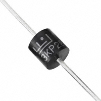
3. 引脚分配: - JEDEC P600模塑塑料外壳,轴向引脚,可焊性符合MIL-STD-750,方法2026。

4. 参数特性: - 峰值功率耗散:在Ta=25°C,τ=1ms时,最小值为3000W。 - 峰值脉冲电流:根据10/1000us波形,具体值见下表。 - 稳态功率耗散:在T=75°C,引脚长度0.375"(9.5mm)时为8.0W。 - 峰值正向浪涌电流:8.3ms单半正弦波,250A。 - 工作与储存结温范围:-55至+175°C。

5. 功能详解: - 瞬态电压抑制器是硅PN结器件,设计用于吸收与电源干扰、开关和感应照明效应相关的高电压瞬态。该系列产品电压范围从5.0伏至220伏。

6. 应用信息: - 3KP系列产品被设计用于开关电源的输出保护,能够承受高电平的峰值电流,允许在短路前断路器跳闸或熔断器熔断,从而让用户能够重置断路器或更换熔断器并继续操作。

7. 封装信息: - R-6或P600封装,具体尺寸以英寸和毫米表示。
3KP10 价格&库存

很抱歉,暂时无法提供与“3KP10”相匹配的价格&库存,您可以联系我们找货

免费人工找货