Specifications are subject to change. Please refer to the current datasheet on www.grayhill.com for the most current published specifications for this product.
Surface Mount DIP Switches
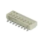
Series 90HB
SPST, Low Profile
FEATURES
• Compatible with SMT Assembly,
Including Infrared Reflow and
Vapor-Phase
• Reliable Spring and Ball Contact
DIMENSIONS
In inches (and millimeters)
Top View–Gull Wing
SWITCH IS PACKAGED
AS SHOWN HERE
WITH ALL
O N
POSITIONS ON
DIP Switches
1
2
.020 ± .002
(0,51 ± 0,05) TYP.
.052 ± .002
(1,32 ± 0,13) TYP.
.085 ± .005
(2,16 ± 0,13) TYP.
Gull Wing
3
4
5
6
7
8
.290 (7,37)
MAX.
CL C
L
.100 ± .005
(2,54 ± 0,13)
TYP.
Recommended PC Pad Dimensions–Gull Wing
CL CL
.395
± .010
(10,03
± 0,25)
.012 ± .002
(0,30 ± 0,05)
.160 ± .005
(4,19 ± 0,13)
LENGTH ± .010 (0,25)
SEE CHART
.004
(0,10)
.190
(4,83)
MAX.
.100 (2,54) TYP.
.070 (1,78) TYP.
J-Bend
.500
(12,7)
TYP.
.250 (6,35) TYP.
.125 (3,18) TYP.
.320 (8,13)
MAX.
.290 (7,37)
MAX.
Recommended PC Pad Dimensions–J-Bend
CL CL
.100 (2,54) TYP.
.070 (1,78) TYP.
.350
(8,90)
TYP.
.150 (3,81) TYP.
.012 ± .001
(0,30 ± 0,03)
TYP.
.250 ± .010
(6,35 ± 0,25)
.160 ± .005
(4,19 ± 0,13)
LENGTH ± .010 (0,25)
SEE CHART
.220
(5,59)
MAX.
.085 ± .005
(2,16 ± 0,13)
TYP.
.020 ± .002
(0,51 ± 0,05) TYP.
.100 ± .010
(2,54 ± 0,25) TYP.
.004
(0,10)
CL CL
.100 (2,54) TYP.
circuitry
As viewed from the top of the switch in the
positions shown in the drawing.
DIP
5
Grayhill, Inc. • 561 Hillgrove Avenue • LaGrange, Illinois 60525-5997 • USA • Phone: 708-354-1040 • Fax: 708-354-2820 • www.grayhill.com
�Specifications are subject to change. Please refer to the current datasheet on www.grayhill.com for the most current published specifications for this product.
Surface Mount DIP Switches
Specifications
Electrical Ratings
Mechanical Ratings
Where Grayhill performance is superior, the MIL
spec is listed in parentheses.
Mechanical Life: 2,000 operations per switch
position
Vibration Resistance: Per Method 204, Test
Condition B , 1mS opening (10 mS allowed)
Mechanical Shock: Per Method 213, Test
Condition A. 1mS opening (10 mS allowed)
Thermal Shock Resistance: Per specification;
no failures; passes contact resistance.
Terminal Strength: Per specification
Thermal Aging: 1,000 hours at 85°C; no
failures.
Environmental Ratings
cleaning is not recommended.
Materials and Finishes
Meets all requirements of MIL- S-83504**.
Operating Temperature Range: -40°C to +
85°C
Storage Temperature Range: -40°C to +
85°C
Moisture Resistance: Per MIL-STD-202,
Method 106.
Shorting Member (Ball): Brass, gold-plate
over nickel barrier.
Base Contacts: Copper alloy, gold-plate
over nickel barrier.
Terminals: Copper alloy, matte tin plated over
nickel barrier.
Non-Conductive Parts: Thermoplastic
(UL94V-O)
Soldering Information
Tape and Reel Packaging
Solderability: Per MIL-STD-202, Method 208
Soldering Heat Resistance: Per MIL-S-83504,
six second test.
Recommended Processing Temperature:
220°C–230°C (1 pass—260°C maximum)
Processing Position: Switch is to be processed
with all actuators in the closed (on) position as
shipped.
Fluxing: Per EIA RS-448-2 with flux touching
switch body.
Cleaning: Passes immersion test using water/
detergent. Acceptable solutions include 1-1-1
trichlorethane, freon, (TF, TE, or TMS), isopropyl
alcohol, detergent (140°F maximum). Terpene
acceptable for Series 90 only. Solutions which are
not recommended include acetone, methylene
chloride, freon TMC. High pressure aqueous
Ordering Information
Tape Seal Integrity: Passes gross leak test
using 125°C flourinert for 20 seconds minimum.
Reference MIL-STD-202, Method 112
Tape Seal: Polyimide film
Tape and Reel Packaging
Meets requirements of
EIA 481-2 or EIA 481-3
13 INCH
DIAMETER REEL
CONDUCTIVE
PLASTIC EMBOSSED
TAPE
DIRECTION
OF FEED
16mm
24mm
TAPE
16mm
32 &
44mm
TAPE
Series
Terminal Style: W = Gull Wing, J = J-Bend
RoHS compliant
90HBW02PRT
Packaging: R = Tape and reel packaging (750 switches/reel)
Blank = Tube packaging (each tube is 19.5" long)
Seal: P = Polyimide Seal
Blank = No Seal
Number of Positions: 02 through 10
No. of
Positions
Length
Inches
Length
Metric
Number
Per Tube
2
3
4
5
6
7
8
9
10
.270"
.370"
.470"
.570"
.670"
.770"
.870"
.970"
1.070"
6,9 mm
9,4 mm
11,9 mm
14,5 mm
17,0 mm
19,6 mm
22,1 mm
24,6 mm
27,2 mm
60
47
37
31
26
23
20
18
16
PIN ONE LOCATION
Each reel has a 15.750 inch (390 mm)
minimum leader and a 6.30 inch (160 mm)
minimum trailer.
Available from your local Grayhill Distributor. For prices and discounts, contact a local Sales Office,
an authorized local Distributor or Grayhill.
** Note: 100% matte tin terminal plating does not meet MIL-S-83504 for lead content.
**Style "GB" contains 30µ gold plated terminals.
Grayhill, Inc. • 561 Hillgrove Avenue • LaGrange, Illinois 60525-5997 • USA • Phone: 708-354-1040 • Fax: 708-354-2820 • www.grayhill.com
DIP
6
DIP Switches
Make-and-break Current Rating: 2,000
operations per switch position at these resistive
loads:10 mA, 30 Vdc; or 10 mA, 50 mVdc; 10 mA,
50 mVdc; or 25 mA, 24 Vdc; or 100 mA,6 Vdc.
Contact Resistance: (measured at 10 mA, 50
mVdc). Initial: 20 mohms maximum, After Life:
100 mohms maximum
Insulation Resistance: Minimum, at 100 Vdc
between adjacent closed contacts and also
across open switch contacts.
Initial (Mohms): 5,000, After Life (Mohms):
1,000
Dielectric Strength: Minimum voltage (AC
RMS) measured between adjacent closed
contacts and also across open switch
contacts.
lnitial: 500 volts, After Life: 500 volts
Current Carry Rating: 3A maximum rise of
20°C
Switch Capacitance: 2 pF at 1 megahertz
�Specifications are subject to change. Please refer to the current datasheet on www.grayhill.com for the most current published specifications for this product.
Grayhill DIP Switch Processing Information
The information provided within is intended as processing guidelines for the assembly, soldering, cleaning, and use of Grayhill DIP switches. This
information supersedes any other process information that is available in Grayhill Inc. catalogs or data sheets as related to Grayhill Inc. standard
DIP switch products. Please contact Grayhill Inc. for any questions related to the information in this document.
Mounting
Unless otherwise noted, Grayhill DIP switches are shipped with slides or rockers in the ON position and rotary DIP switches are shipped with the
actuators in the 0 position. It is recommended that they be solder processed in those positions to ensure proper performance without issue.
Soldering
WAVE SOLDER: Switches that can be processed using wave solder equipment (thru hole soldering) are as follows:
Grayhill Series 76SB, 76PSB, 76PSB, 76RSB, 76SC, 76RSC, 76RSD, 76SD, 76STC, 76STD, 78B, 78RB, 78F, 78G, 78H, 78J, 78K, 90B, 94H
(thru hole models), and 94R
Wave soldering guidelines: Solder wave temperature is 260°C. max. for 5 seconds max. (0.063” thick PCB). Exposure to flux should be kept to a
minimum.
Manual soldering guidelines (for thru hole switches): Soldering temperature is 350C for soldering iron tip with 3 seconds maximum of dwell time.
REFLOW SOLDER: Switches that can be processed using reflow process equipment are as follows:
Grayhill Series 76HP, 78HF, 78HJ, 90B, 90HB, 94H, 94R, 97C, and 97R
Reflow soldering guidelines: Soldering temperature is 260C max. for 5 seconds, with a maximum of two reflow cycles at the maximum
conditions. Switches should be allowed to cool for 3 to 5 minutes between reflow cycles. Reflow soldering should not be done to any Grayhill
DIP switch products not listed directly above as the exposure to higher surface temperatures could cause permanent deformation of the plastic
materials.
Recommended Maximum Soldering Conditions:
Reflow Soldering
Profile:
(260°C
Peak Temperature)
PCB Cleaning
In-line DIP switches that are tape sealed can be processed using certain washing processes as described below. Tape sealed switches can typically
be identified by a suffix of ST or PT that follows after the series, switch style, and number of position identifiers (i.e., 76SB08ST). Non-tape sealed
switches should not be subjected to any washing processes as they can introduce contaminants into the contact area of the switches. Rotary DIP
products (94H & 94R) are internally sealed and can be processed the same as tape sealed products.
Tape sealed and rotary DIP switch products are qualified for immersion cleaning processes using alcohol or detergent based cleaning solvents at
temperatures up to 140°F. maximum. Tape seal products must have the tape seal undisturbed until after any cleaning process. Cleaning processes
that use ultrasonic agitation or that use pressurized sprays can defeat the tape and / or internal seals and allow contamination of the switches. They
are not recommended for use on inline or rotary DIP products. Switches should not be washed directly after a soldering process. There should be
a delay of at least three minutes to allow adequate time for cooling after soldering.
Tape seal integrity: Inline DIP products that are tape sealed are tested to meet and pass a gross leak test using 125°C Fluorinert for 20 seconds
minimum. Reference MIL-202, Method 112.
Tape seal material:
76,78: Polyester film, rated to 170°F. maximum temperature
90: Polyimide film, rated to 260°C. maximum temperature
www.grayhill.com
Bulletin 1234
Rev 08/14
�Specifications are subject to change. Please refer to the current datasheet on www.grayhill.com for the most current published specifications for this product.
PRODUCT ADVISORY NOTICE
KEEPING YOU INFORMED OF PRODUCT CHANGES
To:
All Customers, Sales Representatives and Distributors
Date:
December 28, 2018
Subject:
90 Series Floor Life Reset Instruction Change
This Product Advisory Notice is to alert you that Grayhill is modifying the 90 Series DIP Switch Shelf Reset
Instructions. Please forward this notification to the appropriate person(s) in your organization.
Description of Change
All Grayhill DIP switch products that are labelled as moisture sensitive shall be recommended to be baked
at a lower temperature profile than what is recommended per J-STD-033C. This standard applies to SMT
components in general, and Solid State Surface product specifically. Internal to J-STD-033C, baking
temperatures for floor life reset are specified based on the overall package body thickness; however, this
standard in practice tends to apply to non-mechanical product. The recommended temperature based on
J-STD-033C is 125°C; this temperature has been determined to be overly aggressive. In this nature, JSTD-033C should be disregarded. Additionally, NOTE 5 on the MSID Label of Grayhill’s packaging / reel
shall be also disregarded.
Due to the mechanical nature of Grayhill’s product, the temperature recommended per J-STD-033C
causes a breakdown in the lubricant used in the switch body and contributes to the following conditions:
-
Oil separation and leeching of lubricant which can potentially impact pick-and-place applications
through increased surface tension between the carrier tape pocket and the switch body
Grayhill has NOT seen any evidence of the following conditions caused by the oil separation condition
described above:
-
Impact on switch solderability.
Long-term impact on Grayhill product life.
Long-term impact on additional components exposed to oil from switch lubricant.
The lubricant used in the construction of this switch exhibits a stable chemical nature and is non-reactive
under typical conditions of use, storage and transport.
Grayhill recommends the baking procedure for factory floor life reset to be 60°C ±2°C for 26 -28 hours.
This temperature is not to be exceeded. Longer drying times may be used; however, they shall not exceed
44 hours. The ideal floor life reset process would be to use a dry box utilizing vacuum drying procedures
as opposed to heat drying applications.
Grayhill believes that the only affected products are parts that have been opened and removed from their
original packaging and have been exposed to a floor-life reset bake profile either in excess of 100°C or
longer than 48 hours. All other products that have not been removed from original packaging (or products
that have been reset using a temperature below 100°C or less than 48 hours) have NOT been shown to
exhibit any issues. Grayhill believes this product to be fit for use. Additionally, product that has been baked
in excess of the procedure recommended herein shall also be deemed generally fit for use in cases where
typical automated production processes and schedules are not affected.
561 Hillgrove Avenue • LaGrange, Illinois • 60525-5997 • Ph: 708.354.1040 • Fax: 708.354.2820
www.grayhill.com
Bulletin #1312
Page 1
12/28/2018
�Specifications are subject to change. Please refer to the current datasheet on www.grayhill.com for the most current published specifications for this product.
PRODUCT ADVISORY NOTICE
KEEPING YOU INFORMED OF PRODUCT CHANGES
Effective Date
1/1/2019
Part Numbers Affected
Action Required
None. Please contact your Grayhill, Inc. Sales Associate for further information.
561 Hillgrove Avenue • LaGrange, Illinois • 60525-5997 • Ph: 708.354.1040 • Fax: 708.354.2820
www.grayhill.com
Bulletin #1312
Page 2
12/28/2018
�Mouser Electronics
Authorized Distributor
Click to View Pricing, Inventory, Delivery & Lifecycle Information:
Grayhill:
90HGBW06T 90HGBW06PRT 90HGBW03RT 90HGBW02RT 90HGBW08RT 90HGBW08PRT 90HGBW10PT
90HGBW08PT 90HGBW02PRT 90HGBW04PT 90HGBW05PT 90HGBW03PRT 90HGBW02PT 90HGBW03PT
90HGBW06RT 90HGBW04PRT 90HGBW05PRT 90HGBW06PT 90HGBW04RT 90HGBW05RT 90HGBW10RT
�