TVS Diodes
Axial Leaded - 20kA > AK20-Y Series
AK20-Y Series
RoHS
Pb
e4
Descriptions
The AK20-Y series of high power TVS diode is specially
designed for meeting severe surge test environment of
both AC and DC line protection applications. It features a
very fast response and ultra low clamping characteristics
as compared to MOVs (Metal Oxide Varistors). It
accomplishes this by virtue of the Littelfuse FoldbackTM
technology,which provides a clamping voltage lower
than the avalanche voltage (but above the rated working
voltage); therefore, any voltage rise due to increased
current conduction is maintained at a minimum magnitude,
providing the best possible protection level. These AK
components can be connected in series and / or parallel
to create a very high surge current protection solution.
Features
Agency Recognitions
Agency
• No wear-out nor degrade
surge rating over multiple
transient events as long
as within surge capability
• Ultra high power rating
• Very low clamping voltage
• Both reflow and wave
soldering capable
• Ultra compact: less
than one-tenth the size
of traditional discrete
solutions
•�Sharp breakdown voltage
• Low slope resistance
• Bi-directional
• Foldback technology for
superior clamping factor
• Symmetric lead width
for easy soldering during
assembly
Agency File Number
E128662
Maximum Ratings and Thermal Characteristics
(TA=25OC unless otherwise noted)
Parameter
Symbol
Value
Unit
°C
Operating Storage Temperature Range
TSTG
-55 to 150
Operating Junction Temperature Range
TJ
-55 to 125
ºC
Current Rating1
IPP
20
kA
Note:
1. Rated IPP measured with 8/20μs pulse as defined in IEC 61000-4-5 2nd edition.
Functional Diagram
• �IEC 61000-4-2 ESD 15 kV
(air), 8 kV (contact) rating
• �Lightning, 20 kA (8/20 as
defined in IEC 61000-4-5
2nd Edition)
• �EFT protection of data
lines in accordance with
IEC 61000-4-4
• UL Recognized
compound meeting
flammability rating V-0
•�Halogen-free and RoHS
compliant
• Glass passivated junction
• Pb-free E4 means 2nd level
interconnect is Pb-free
and the terminal finish
material is silver (IPC/
JEDEC J-STD-609A.01)
Bi-directional
Electrical Characteristics (T =25°C unless otherwise noted)
A
Part
Numbers
Part
Marking
Max.
Standoff
Reverse
Voltage
Leakage
(VSO)
(IR) @VSO
Volts
(µA)
Reverse
Test
Max. Clamping Voltage
Breakdown
Typical Voltage (V ) Current
VCL @ Peak Pulse Current (IPP)
BR
I
IR @
T
@ IT
85OC
VCL
IPP
VCL
IPP
(µA)
Min
Max
(mA) (8/20μs) (8/20μs) (10/350μs) (10/350μs)
Volts Volts
Volts
Amps
Volts
Amps
Max.
Max. Temp
Capacitance
Coefficient
0V Bias
of VBR
10kHz
(%/OC)
(nF)
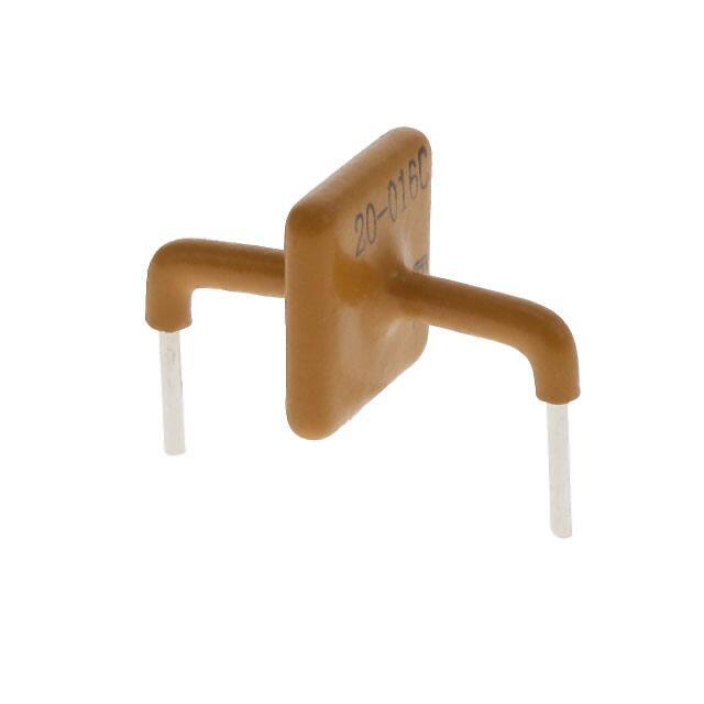
AK20-016C-Y
20-016C
16
5
15
17.5
19.3
10
30
20,000
28
3,200
0.1
50
AK20-058C-Y
20-058C
58
5
15
64.0
70.0
10
120
20,000
107
3,200
0.1
15
AK20-063C-Y
20-063C
63
5
15
68.0
75.0
10
125
20,000
110
3,200
0.1
12
AK20-066C-Y
20-066C
66
5
15
72.0
80.0
10
130
20,000
120
3,200
0.1
12
AK20-076C-Y
20-076C
76
5
15
85.0
95.0
10
160
20,000
145
3,200
0.1
12
Note: using 8/20 waveshape as defined in IEC 61000-4-5 2nd edition
©2020 Littelfuse, Inc.
Specifications are subject to change without notice.
Revision: JC.12/28/20
�TVS Diodes
Axial Leaded - 20kA > AK20-Y Series
Soldering Parameters
Lead–free assembly
Pre Heat
- Temperature Min (Ts(min))
150°C
- Temperature Max (Ts(max))
200°C
Ramp-up
TL
60 – 120 secs
- Time (min to max) (ts)
Average ramp up rate (Liquidus Temp (TL) to peak 3°C/second max
3°C/second max
TS(max) to TL - Ramp-up Rate
Reflow
tp
TP
- Temperature (TL) (Liquidus)
217°C
- Time (min to max) (ts)
60 – 150 seconds
Peak Temperature (TP)
260+0/-5 °C
Time within 5°C of actual peak Temperature (tp)
30 seconds max
Ramp-down Rate
6°C/second max
Time 25°C to peak Temperature (TP)
8 minutes max.
Do not exceed
260°C
Temperature (T)
Reflow Condition
Critical Zone
TL to TP
tL
Ts(max)
Ramp-down
Ts(min)
ts
Preheat
25˚C
t 25˚C to Peak
Time (t)
Physical Specifications
Weight
Contact manufacturer
Case
UL Recognized epoxy meeting flammability
rating V-0
Terminal
Silver plated leads, solderable per
MIL-STD-750 Method 2026
Flow Soldering (Solder Dipping)
Pb - Free assembly
Pre Heat
- Temperature Min
140°C
- Temperature Max
160°C
Time to Pre-Heat Temp
60-150 seconds
Average ramp up rate to Pre-Heat Temp
5°C/second max
Peak Temperature
260+0/-5 °C
Average ramp up rate (Tpre-heat to Tp)
5°C/second max
Time within actual peak Temperature Max
6 seconds
Ramp-down Rate
5°C/second max
tP
Temperature
Wave soldering condition
TP
Ramp-up
TS
Ramp Down
Pre-heat
time to peak temperature
Time (t)
Ratings and Characteristic Curves (T =25°C unless otherwise noted)
A
Figure 2 - Typical VBR Vs Junction Temperature
12
10
100
Percent of VBR Change
Percent of Rated Value
Figure 1- Peak Power Derating
80
60
40
20
8
6
4
2
0
-2
-4
-6
-8
0
0
25
50
75
100
TJ - Initial Junction Temperature (ºC)
125
-50
-25
0
25
50
75
100
125
Junction Temperature(Tj )
©2020 Littelfuse, Inc.
Specifications are subject to change without notice.
Revision: JC.12/28/20
�TVS Diodes
Axial Leaded - 20kA > AK20-Y Series
Ratings and Characteristic Curves (T =25°C unless otherwise noted) (Continued)
A
Figure 4 -Surge Response (8/20 Surge Current Waveform)
IPP – Peak Pulse Current – %IPP
Figure 3 - Pulse Waveform
Peak
Value
100
tr = rise time to peak value
td = decay time to half value
Voltage
tr x td =8/20µs
50
Half Value
0
0
td
tr
Current
t – Time (µs)
Note:
Its Foldback TM technology provides a clamping voltage lower than the avalanche voltage (but above the
rated working voltage). Also use similar clamping diagram showing the actual voltage waveshape reaction
of this foldback technology as shown in attached text at the nd of this document. Please note this is
specifically for a 10 kA rated AK, so we need an actual waveshape for this 20 kA rated component..
Dimensions
A
G
L2
Dimensions
Inches
Millimeters
A
0.950±0.030
24.15±0.8
B
0.095±0.024
2.4±0.60
C
0.236±0.040
6.00±1.0
D
0.630±0.055
16.0±1.4
E
0.050±0.002
1.27±0.05
F
0.587±0.055
14.9±1.4
G - 016C
0.157 max.
4.00 max.
0.307 max.
7.80 max.
F
L1
D
C
B
E
C
L1= L2 tolerance +/- 0.04 inch (1.0 mm)
L1/L2
Packing Options
Part Numbering System
Component
Package
Quantity
Packaging
Option
AK20-XXXX-Y
AK Package
56pcs/Box
Bulk
AK20-XXXX-Y-12
AK Package
12pcs/Box
Bulk
Part Number
G - 058C/063C
066C/076C
AK20 - XXXX -Y
Yellow Coating
Series Type
Stand Off Voltage
(Please Refer to Electrical
Characteristics Chart)
Part Marking System
Part Marking
YWW
Trace Code Marking
Y:Year Code
WW: Working Week Code
Type 1 - Side View
Apply to P/N listed below:
AK20-076C-Y
20-xxxx
LF
Littelfuse Logo
Littelfuse Logo
LF YWW
20-XXXX
Apply to P/N listed below:
AK20-016C-Y
AK20-058C-Y
AK20-063C-Y
AK20-066C-Y
Part Marking
Trace Code Marking
Y:Year Code
WW: Working Week Code
Type 2- Top View
Disclaimer Notice - Information furnished is believed to be accurate and reliable. However, users should independently evaluate the suitability of and test each product selected for their own
applications. Littelfuse products are not designed for, and may not be used in, all applications. Read complete Disclaimer Notice at http://www.littelfuse.com/disclaimer-electronics.
©2020 Littelfuse, Inc.
Specifications are subject to change without notice.
Revision: JC.12/28/20
�
很抱歉,暂时无法提供与“AK20-016C-Y”相匹配的价格&库存,您可以联系我们找货
免费人工找货