Thyristors
Surface Mount > 200 - 600V > C106 Series
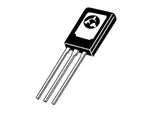
C106 Series
Pb
Description
Glassivated PNPN devices designed for high volume
consumer applications such as temperature, light, and
speed control; process and remote control, and warning
systems where reliability of operation is important.
Features
• Glassivated Surface for
Reliability and Uniformity
• Power Rated at
Economical Prices
• Practical Level
Triggering and Holding
Characteristics
• Flat, Rugged, Thermopad
Construction for Low
Thermal Resistance, High
Heat Dissipation and
Durability
• Sensitive Gate Triggering
• These are Pb−Free
Devices
Functional Diagram
Pin Out
G,3
A,2
TO-225A A
Case 77
Style 2
K,1
Additional Information
3 2
1
Datasheet
Resources
Samples
© 2020 Littelfuse, Inc.
Specifications are subject to change without notice.
Revised: 08/11/20
�Thyristors
Surface Mount > 200 - 600V > C106 Series
Maximum Ratings (TJ = 25°C unless otherwise noted)
Rating
Peak Repetitive Off−State Voltage
(Sine Wave, 50−60 Hz, RGK = 1 K,
TC = −40° to 110°C)
C106B
C106D, C106D1*
C106M
On-State RMS Current (180° Conduction Angles, TC = 80°C)
Symbol
Value
Unit
VDRM,
VRRM
200
400
600
V
IT
4.0
A
(RMS)
Average On−State Current (180° Conduction Angles, TC = 80°C)
IT(AV)
2.55
A
Peak Non-Repetitive Surge Current
(1/2 Cycle, Sine Wave, 60 Hz, TJ = +25°C)
ITSM
20
A
Circuit Fusing Considerations (t = 8.3 ms)
I2t
1.65
A2s
Forward Peak Gate Current
(Pulse Width 1.0 sec, TC = 80°C)
IGM
0.2
A
Forward Peak Gate Power (Pulse Width ≤ 1.0 �µsec, TC = 80°C)
PGM
0.5
W
Forward Average Gate Power (Pulse Width ≤ 1.0 �µsec, TC = 80°C)
PG(AV)
0.1
W
Operating Junction Temperature Range
TJ
-40 to +110
°C
Storage Temperature Range
Tstg
-40 to +150
°C
_
6.0
in. lb.
Mounting Torque (Note 2)
Stresses exceeding Maximum Ratings may damage the device. Maximum Ratings are stress ratings only. Functional operation above the Recommended Operating Conditions is not implied. Extended exposure to stresses above the
Recommended Operating Conditions may affect device reliability.
1. VDRM and VRRM for all types can be applied on a continuous basis. Ratings apply for zero or negative gate voltage; however, positive gate voltage shall not be applied concurrent with negative potential on the anode. Blocking voltages
shall not be tested with a constant current source such that the voltage ratings of the devices are exceeded.
2. Torque rating applies with use of torque washer (Shakeproof WD19523 or equivalent). Mounting Torque in excess of 6 in. lb. does not appreciably lower case-to-sink thermal resistance. Main terminal 2 and heat-sink contact pad
are common.
Thermal Characteristics
Rating
Symbol
Value
Unit
RƟJC
RƟJA
3.0
75
°C/W
TL
260
°C
Junction−to−Case (AC)
Junction−to−Ambient
Thermal Resistance,
Maximum Lead Temperature for Soldering Purposes, 1/8” from case for
10 seconds
Electrical Characteristics - OFF (TJ = 25°C unless otherwise noted)
Characteristic
Peak Repetitive Forward or Reverse Blocking Current
(VAK = Rated VDRM or VRRM, RGK = 1 Ωk)
Symbol
TJ = 25°C
TJ = 110°C
IDRM, IRRM
Min
Typ
Max
Unit
_
_
10
μA
–
–
100
µA
Typ
Max
Unit
V
Electrical Characteristics - ON (TJ = 25°C unless otherwise noted)
Characteristic
Peak Forward On-State Voltage (Note 3) (ITM = 4 A)
Gate Trigger Current (Continuous dc)
(VD = 12 V, RL = 100 Ω, All Quadrants)
TJ = 25°C
TJ = -40°C
Peak Reverse Gate Voltage (IGR = 10 �µA)
Gate Trigger Voltage (Continuous dc)
(VD = 12 Vdc, RL = 100 Ω, TC = 25°C)
Holding Current
(VD = 12 Vdc)
(Initiating Current = 20 mA, RGK = 1 kΩ)
Min
VTM
–
–
2.2
_
15
200
–
35
500
IGT
VGRM
TJ = 25°C
TJ = -40°C
Gate Non−Trigger Voltage (Continuous dc) (Note 4)
(VAK = 12 V, RL = 100
(VAK = 12 V, RL = 100 , TJ = 110°C), TJ = 110°C)
Latching Current
(VAK = 12 V, IG = 20 mA, RGK = 1 kΩ)
Symbol
VGT
VGD
TJ = 25°C
TJ = -40°C
IL
TJ = 25°C
TJ = -40°C
TJ = +110°C
IH
–
–
6.0
0.4
0.60
0.8
0.5
0.75
1.0
0.2
_
_
_
0.20
5.0
–
0.35
7.0
_
0.19
3.0
_
0.33
6.0
_
0.07
2.0
µA
V
V
V
mA
mA
© 2020 Littelfuse, Inc.
Specifications are subject to change without notice.
Revised: 08/11/20
�Thyristors
Surface Mount > 200 - 600V > C106 Series
Dynamic Characteristics
Characteristic
Critical Rate-of-Rise of Off State Voltage
(VAK = Rated VDRM, Exponential Waveform, RGK = 1kΩ,TJ = 110°C)
Symbol
Min
Typ
Max
Unit
dv/dt
–
8.0
−
V/µs
3. Pulse Test: Pulse Width ≤ 2.0 ms, Duty Cycle ≤ 2%.
4. RGK is not included in measurement.
Voltage Current Characteristic of SCR
Symbol
VDRM
Peak Repetitive Forward Off State Voltage
IDRM
Peak Forward Blocking Current
VRRM
Peak Repetitive Reverse Off State Voltage
IRRM
Peak Reverse Blocking Current
VTM
Maximum On State Voltage
IH
+Current
Parameter
Quadrant 1
Main Terminal 2 +
VTM
On State
IRRM at VRRM
Holding Current
IH
Quadrant 3
Main Terminal 2 -
IH
Off State
+Voltage
IDRM at VDRM
VTM
© 2020 Littelfuse, Inc.
Specifications are subject to change without notice.
Revised: 08/11/20
�Thyristors
Surface Mount > 200 - 600V > C106 Series
Figure 1. Average Current Derating
Figure 2. Maximum On-State Power Dissipation
Figure 3. Typical Gate Trigger Current vs. Junction Temp
Figure 4. Typical Holding Current vs. Junction Temp
Figure 5. Typical Gate Trigger Voltage vs. Junction Temp
Figure 5. Typical Latching Current vs. Junction Temp
© 2020 Littelfuse, Inc.
Specifications are subject to change without notice.
Revised: 08/11/20
�Thyristors
Surface Mount > 200 - 600V > C106 Series
Part Marking System
Dimensions
A1
A
TO-225A A
Case 07 7
Style 2
Q
E
ØP
D
PIN4
BACKSIDE TAB
2
3
1. Cathode
2. Anode
3. Gate
L1
1
b1
L
Y
M
A
XX
C106xx
xx
G
b2 x2
b
e
Dim
e
C106xxG
YMAXX
=Year
=Month
=Assembly Site
=Lot Serial Code
=Device Code
=B, D, D1, M, M1
=Pb-Free Package
c
Inches
Min
Pin Assignment
Millimeters
Max
Min
Max
1
Cathode
2
Anode
3
Gate
A
0.102
0.110
2.60
2.80
A1
0.047
0.055
1.20
1.40
b
0.028
0.034
0.70
0.86
b2
0.028
0.034
0.70
0.86
c
0.019
0.022
0.49
0.57
D
0.417
0.449
10.60
11.40
E
0.291
0.323
7.40
8.20
Device
e
0.090 TYP
L
0.551
14.00
16.00
C106DG
L1
0.091
0.106
2.30
2.70
C106D1G*
P
0.118
0.134
3.00
3.40
C106MG
C106M1G*
2.29 TYP
0.630
Package
Shipping
C106BG
Q
0.142
0.157
3.60
4.00
b1
0.047
0.055
1.2
1.4
1. DIMENSIONING AND TOLERANCING PER ANSI Y14.5M, 1982.
2. CONTROLLING DIMENSION: INCH.
3. 077-01 THRU -08 OBSOLETE, NEW STANDARD 077-09.
Ordering Information
TO225AA
(Pb-Free)
C106MTG
2500 Units/Box
60 Units/Tube
1920 Units/Box
*D1 signifies European equivalent for D suffix and M1 signifies
European equivalent for M suffix.
Disclaimer Notice - Information furnished is believed to be accurate and reliable. However, users should independently evaluate the suitability of and test each product selected for their own applications. Littelfuse products are
not designed for, and may not be used in, all applications. Read complete Disclaimer Notice at http://www.littelfuse.com/disclaimer-electronics.
© 2020 Littelfuse, Inc.
Specifications are subject to change without notice.
Revised: 08/11/20
�