Protection Relays
Communication Modules
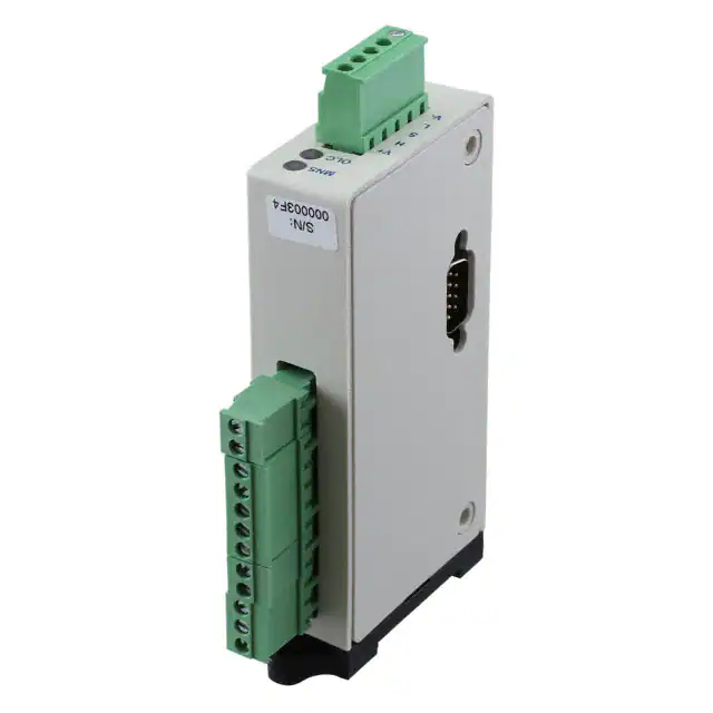
CIO-DN-P/CIO-120-DN-P
Communication link to PLC/SCADA/
monitoring systems
Description
The CIO-DN-P/CIO-120-DN-P are convenient and cost-effective
Devicenet™ interfaces capable of providing discrete control and
monitoring of motor starters, drives and other devices over a
Devicenet™ network.
Features & Benefits
Wiring Diagram
TYPICAL WIRING FOR CIO-DN-P
DIGITAL
INPUTS
REMOTE
RESET
OUTPUT
A
OUTPUT
B
DEPLUGGABLE
TERMINAL BLOCKS
R
DEVICENET MODULE/NETWORK S
TATUS
R
C
I1
I2
I3
REMOTE
RESET
V+
1
I4
OVERLOAD COMM. S
TATUS
CAN L
CIO-DN
4
5
OUTPUT B
DeviceNet Communication and I/O
SCREW TORQUE RATING 0.5 Nm (5 in.-l bs.)
Compact size
3.4” H x 1.0” W x 5.46” D
Easily adapts to existing as well as
new applications
Flexible addressing
standard allows function
as stand-alone interface
or in conjunction with
777 series overload relay
Provides flexibility for control and monitoring
Remote reset option
Additional remote reset input allows user to reset
777 series relays without opening the panel
DIN rail or surface
mountable
Allows installation flexibility
Unpluggable terminal
block connections
Allows user to wire terminal blocks before installing
the module and reduces field wiring
®
LISTED
V-
Specifications
FIGURE 1: Typical Wiring Diagram (CIO-DN-Px, CIO-601CS-DN-P1)
TYPICAL WIRING FOR CIO-120-DN-P
REMOTE
RESET
OUTPUT OUTPUT
A
B
115VAC
DEPLUGGABLE
TERMINAL BLOCKS
DEVICENE T MODULE/NETWORK STATUS
R
R
REMOTE
RESET
V+
C
I1
I2
I3
I4
1
2
3
4
5
INPUTS 1-4
115VAC
OVERLOAD COMM. STATUS
AC COMMON
OUTPUT A
OUTPUT B
PILOT DUTY RATING
480VA @ 240 VAC, B300
5A @ 240 VAC
GENERAL PURPOSE
CAN H
SHEILD
IND. CONT. EQ .
CAN L
784X
DEVICENET
NETWORK
BENEFITS
IND . CON T. EQ.
784X
SHEILD
3
PILOT D UTY RATING
480VA @ 240VAC, B300
5A @ 240VAC
GENERAL PURPOSE
CAN H
DEVICENET
NETWORK
2
OUTPUT A
DIGITAL
INPUTS
FEATURES
SCR EW T ORQUE RATING 0.5 Nm (5 in-lbs.)
V-
FIGURE 2: Typical Wiring Diagram (CIO-120-DN-Px)
Ordering Information
MODEL
LINE VOTAGE
CIO-DN-P
12 to 24VAC
CIO-120-DN-P
90 to 130VAC
© 2016 Littelfuse Protection Relays & Controls
www.littelfuse.com/ciodnp-cio120dnp
LISTED
®
Input Characteristics
Power Requirements
Voltage (nominal)
Current
Power
Digital Inputs
Voltage Range
CIO-DN-P
CIO-120-DN-P
Frequency
Maximum Current
Remote Reset
Output Characteristics
Form A & Form C Contactors
Pilot Duty
General Purpose
General Characteristics
Temperature Range
Relative Humidity
Wire Gauge
Terminal Torque
Hi-Potential Test
(relays to other circuits)
24VDC
137mA (max.)
3.28 W (max.)
12-24 VAC
90-130VAC
50/60Hz
2mA (typical)
24VDC, 10mA (min.), NO pushbutton
480VA @ 240VAC, B300
5A @ 240VAC
-20° to 70°C (-4° to 158°F)
10-95%, non-condensing
Solid or stranded, 12-20 AWG
3 in.-lbs.
(2 x rated V + 1000V for 1 minute)
Rev: 1-A-062716
�Protection Relays
Communication Modules
CIO-DN-P/CIO-120-DN-P
EMC Standards
Electrostatic Discharge (ESD) IEC 61000-4-2, Level 3, 6kV contact, 8kV air
Radio Frequency Immunity,
Radiated
150 MHz, 10V/m
Fast Transient Burst
IEC 61000-4-4, Level 3, 4kV input power
Safety Marks
UL, ULC Listed
UL508 (File #E68520)
CSA
C22.2 (File #46510)
Enclosure
Polycarbonate
Dimensions H 86.36 mm (3.4”); W 25.4 mm (1.0”);
D 138.68 mm (5.46”)
(w/depluggable connectors)
Weight
0.25 lb. (4 oz., 113.4 g)
(w/depluggable connectors)
Mounting Methods
DIN Rail or surface mount (w/two #8 screws)
© 2016 Littelfuse Protection Relays & Controls
www.littelfuse.com/ciodnp-cio120dnp
Rev: 1-A-062716
�
很抱歉,暂时无法提供与“CIO-120-DN-P”相匹配的价格&库存,您可以联系我们找货
免费人工找货- 国内价格 香港价格
- 1+4655.997461+597.22527
- 10+3912.3714410+501.84029