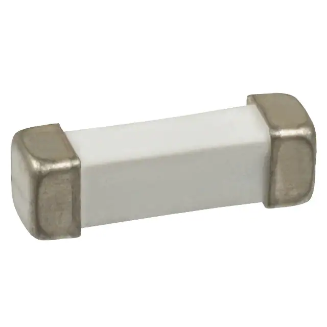
The telecom FT600 fuse helps telecommunications
equipment manufacturers comply with North American
overcurrent protection requirements, including Telcordia
GR-1089, TIA-968-A (formerly FCC Part 68), and
UL60950 3rd edition.
TE Circuit Protection’s telecom fuses offer low
temperature-rise performance under sneak current fault
events to help prevent damage to circuit traces or
multilayer boards, and their low profile and small
Surface-mount Fuses – Telecom Fuses
Surface-mount Fuses
Telecom Fuses
footprint make them suitable for high-density and
space-constrained applications.
Benefits
Features
• High density placement in multi-port system designs
• Lead free materials and RoHS compliant
• Improved temperature rise performance over other
similar surface-mount fuse devices under sneak
current testing
• Halogen free
• The FT600, in conjunction with a thyristor surge
suppression device, assists designers to meet
regulatory standards without additional series
components
(refers to: Brⱕ900ppm, Clⱕ900ppm, Br+Clⱕ1500ppm)
11
• Low profile and small footprint
• The lightning robust surface-mount fuse offers
overcurrent protection in case of power fault events
• Enables the design of equipment complying with
applicable telecom specifications including
UL60950, TIA-968-A, and Telcordia GR-1089
• Low resistance
Applications
• ADSL, ADSL2, ADSL2plus, SHDSL, VDSL linecards and modems
• T1/E1 systems
• Twisted-pair telecom ports requiring Telcordia GR-1089, UL60950 and FCC Part TIA-968-A compliance
103
�Protection Application Guide for Telecommunications and Networking Devices
To use this guide, follow the steps below:
1. Select your equipment type from the guide below.
2. Use the Key Device Selection Criteria (time-to-open, surface temperature) to determine best suitability for your application.
3. Use Agency Specification / Selection Guide to select a specific part number for each application based on the agency requirements.
Key Device Selection Criteria
Application
Specification
Faster
Time-To-Open
Cooler Surface
Temperature
Customer premises equipment, IT equipment
UL 60950
FT600-0500
FT600-2000
Analog modems, V.90 modems,
TIA-968-A
FT600-1250
Access network equipment
Telcordia GR-1089
FT600-1250
FT600-2000
Remote terminals, line repeaters, multiplexers,
TIA-968-A
FT600-1250
FT600-2000
ISDN modems, xDSL modems,
ADSL splitters, phone sets, fax machines,
answering machines, caller ID, internet
appliances, PBX systems, POS terminals, wall plugs
cross-connects, WAN equipment
Central office switching equipment
Telcordia GR-1089
Analog/POTS linecards, ISDN linecards, xDSL modems,
TIA-968-A
ADSL/VDSL splitters, T1/E1 linecards,
multiplexers, CSU/DSU, servers
Note : This list is not exhaustive. TE Circuit Protection welcomes our customers’ input for additional application ideas for overcurrent protection of telecom applications.
Agency Specification/Selection Guide for FT600 Devices
Use the guide below to select FT600 devices appropriate for use in your application. The following pages contain specifications for part
numbers recommended below. FT600 devices enable telecommunication equipment to meet the applicable protection requirements of
these industry specifications. Refer to individual agency specifications for test procedures and circuit schematics. Users should
independently evaluate the suitability of, and test each product for their application.
Family
Product
Lightning
Power Cross
FT600
FT600-0500
TIA-968-A – Types A & B
UL60950, 3rd Ed. – 600VAC, 40A
FT600-1250
Telcordia GR-1089 – Level 1 and 2
Telcordia GR-1089 – 600 VAC, 40A
FT600-2000
TIA-968-A
UL60950
Notes: FT600-1250 and FT600-2000 assist equipment in complying with Telcordia GR-1089 specifications. In-circuit testing is strongly recommended.
The FT600-0500, FT600-1250 and FT600-2000 help meet the UL60950 Power Cross and FCC TIA-968-A 68 lightning surge requirements. Note that Type A tests allow for an
overcurrent protection component to fuse open during the surge.
11
Table FT1 Interrupt Voltage and Current Ratings for FT600 Devices
Typical I2t
(A2s)*
Ampere Rating
(A)
Voltage Rating
(V)
Typical Resistance
(Ω)
FT600-0500
0.50
250
0.50
1
FT600-1250
1.25
250
0.10
16
FT600-2000
2.00
250
0.05
18
Part Number
Note: The FT600-xxxx devices carry 100% of rated current for 4 hours minimum and 250% of rated current for 1 second minimum, 120 seconds maximum.
Resistance measured at 10% of rated current.
*I2t is calculated at 10 ms or less.
Figure FT1 Thermal Derating Curve (Normalized) for FT600 Devices
130
% of Current Rating
120
110
100
90
80
70
-70
-50
-30
-10
10
30
50
Ambient Temperature ˚C
104
RoHS Compliant, ELV Compliant
HF Halogen Free
70
90
110
130
�Surface-mount Fuses – Telecom Fuses
Table FT2 Dimensions for FT600 Devices in Millimeters (Inches)
A
Part Number
FT600-0500
Min.
—
B
Max.
10.2
Min.
—
(0.402)
FT600-1250
—
—
Min.
—
Max.
3.1
(0.122)
10.2
—
(0.402)
FT600-2000
C
Max.
3.1
(0.122)
3.1
—
3.1
(0.122)
10.2
—
(0.402)
Figure
FT2
FT2
(0.122)
3.1
—
3.1
(0.122)
FT2
(0.122)
Figure FT2 Dimension Figures for FT600 Devices
C
A
B
Figure FT3 Typical Time-to-open Characteristics (at 20°C) for FT600 Devices
FT600
A = FT600-0500
B = FT600-1250
C = FT600-2000
Figure FT3
0.500A
100
A
10
1.25A
2A
B
C
11
Time (sec)
1
0.1
0.01
0.001
0.1
1
10
100
1000
Current in Amperes
RoHS Compliant, ELV Compliant
HF Halogen Free
105
�Table FT3 Physical Characteristics and Environmental Specifications for FT600 Devices
Physical Characteristics
Terminal material
Body material
Termination solderability
Silver-plated brass*
Ceramic
Per IEC-60127-4
*FT600 devices use high Pb content solder for internal construction. They are RoHS compliant.
Environmental Specifications
Test
Solder heat withstand
Solvent resistance
Storage temperature
Storage humidity
Conditions
Per MIL-STD-202, Method 210, Test Condition J
Per MIL-STD-202F, Method 215J
ⱕ30°C/ 85% RH
Per MIL-STD-202F, Method 106F
Table FT4 Packaging and Marking Information for FT600 Devices
Part Number
Bag
Quantity
Tape & Reel
Quantity
Standard Package
Quantity
FT600-0500-2
—
2,500
10,000
500
FT600-1250-2
—
2,500
10,000
1250
UL, CSA
FT600-2000-2
—
2,500
10,000
2000
UL, CSA
Part Marking
Agency Recognition
UL, CSA
Note: The -2 designates tape and reel, the package style for this product.
Table FT5 Recommended Pad Layouts for FT600 Devices in Millimeters (Inches) Nominal
Figure FT4
Device
FT600-0500
11
FT600-1250
FT600-2000
A
B
C
D
Figure for Dimensions
FT4
12.6
4.0
3.7
5.2
(0.496)
(0.157)
(0.145)
(0.204)
12.6
4.0
3.7
5.2
(0.496)
(0.157)
(0.145)
(0.204)
12.6
4.0
3.7
5.2
(0.496)
(0.157)
(0.145)
(0.204)
D
C
FT4
B
FT4
A
Solder Reflow and Rework Recommendations for FT600 Devices
Rework
• If a device is removed from the board, it should be discarded and
replaced by a new device
Figure FT5
300
Temperature (˚C)
Solder Reflow
• Recommended reflow methods: IR, vapor phase oven, hot air oven
• Devices can be cleaned using standard industry methods and solvents
Preheating
Soldering
Cooling
250
200
150
100
50
0
30-90
10 to 20
Time (s)
106
RoHS Compliant, ELV Compliant
HF Halogen Free
120
�Surface-mount Fuses – Telecom Fuses
Table FT6 Tape and Reel Specifications for FT600 Devices
Dimension
Description
EIA Mark
Dimension (mm)
Tolerance
Carrier tape width
W
24
±0.3
Sprocket hole pitch
P0
4
±0.1
P1
8
±0.1
P2
2
±0.1
A0
3.68
±0.1
B0
10.44
±0.1
D0
1.5
+0.1 / -0.0
F
11.5
±0.1
E1
1.75
±0.1
Sprocket hole diameter
Tape thickness
T max.
0.3
±0.05
K0
3.25
+1.0 / -0.05
Reel diameter
A max.
331.5
Core diameter
N min.
98.5
Reel Dimensions
Space between flanges less devices
Reel width
W0
25
W1 max.
31
±0.5
Figure FT6 EIA Referenced Taped Component Dimensions for FT600 Devices
P0 Note 1
T
A
P2 Note 6
E1
Notes:
1. 10 sprocket hole pitch cumulative tolerance ±0.2
D0
2. Allowable camber to be 1mm/250mm
F Note 6
W
3. Material: Black conductive
4. A0 and B0 measured on a plane 0.3mm above the
bottom of the pocket
B0
K0
P1
11
5. K0 measured from the plane on the inside bottom
of the pocket to the top surface of the carrier
6. Pocket position relative to sprocket hole measured
as true position of pocket, not pocket hole
7. Quantity per reel to be 174m
A0
A
Figure FT7 EIA Referenced Reel Dimensions for FT600 Devices
W1
W0
ø13.2±0.2
(0.52±0.008)
A
N
120°
17.2±0.2
(0.677±0.008)
2.2±0.2
(0.087±0.008)
Detail A
See “Detail A”
RoHS Compliant, ELV Compliant
HF Halogen Free
107
�Part Numbering System for FT600 Devices
FT 600 - 1250 -2
Packaging
-2
= Tape and Reel
Current in Amperes
1250 = 1.25
0500 = 0.500
2000 = 2.00
Voltage Rating
Product Family
11
Warning :
All information, including illustrations, is believed to be accurate and reliable. Users, however, should independently evaluate the suitability of and
test each product selected for their application. Tyco Electronics Corporation and/or its Affiliates in the TE Connectivity Ltd. family of companies
(“TE”) makes no warranties as to the accuracy or completeness of the information, and disclaims any liability regarding its use.TE’s only obligations
are those in the TE Standard Terms and Conditions of Sale for this product, and in no case will TE be liable for any incidental, indirect, or
consequential damages arising from the sale, resale, use, or misuse of the product. Specifications are subject to change without notice. In
addition, TE reserves the right to make changes to materials or processing that do not affect compliance with any applicable specification without
notification to Buyer.
108
RoHS Compliant, ELV Compliant
HF Halogen Free
�


 工商网监
湘ICP备2023018690号
工商网监
湘ICP备2023018690号
