Surge Protection Module
LED Lighting Surge Protection Module > LSP05G Europe Version
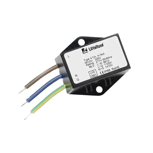
LSP05G European Version Module Series
RoHS
Description
Agency Approvals
Agency
Standard
Agency File Number
UL1449
E320116
Features
Applications
• Outdoor and Commercial
LED Lighting
• Roadway lighting
• Traffic lighting
• Digital signage
•
•
•
•
•
Wall wash lighting
Parking garage lighting
Flood lighting
Tunnel lighting
Street lighting
Additional Information
Datasheet
Littelfuse’s LSP05G European version thermally protected
Surge Protective Device is a self-protected device specially
designed to be used in outdoor and commercial LED lighting
fixtures for transient overvoltage protection. It has been
developed with Littelfuse’s thermally protected varistor
technology. Its built-in thermal disconnect function provides
additional protection to prevent catastrophic failure and fire
hazard even under extreme circumstances of varistor end-oflife or sustained over-voltage conditions. It also provides high
line-to-earth/ground resistance, facilitating faster production
line testing.
LSP05G series connected option allows clear indication
of thermal fault protection by disconnecting power to the
luminaire, thereby signaling SPD module replacement.
The LSP05G Surge Protective Device facilitates product
compliance to IEEE C62.41.2 Location Category C Low.
Resources
Samples
• Maximum Discharge
Current 10kA, 8/20µs
• Meets ANSI C136.2
Enhanced Level
10kV/5kA and IEEE
C62.41.2 Location
Category C Low
Exposure
• Thermally Protected
Varistor technology
• Parallel and Series
Connected SPD Options
• IP66 Water-proof
and Dust-proof
• UL1449 Recognized
• IEC 61643-11 Class
II and EN 61643-11
Type 2 compliant.
• IEC CB Scheme Certificate
•
•
•
•
•
NL-37684 available for 240V
and NL-40516 for 277V
Compact form factor
with mounting tabs
240Vac and 277Vac
are available for Class I
and Class II installation
based on IEC luminaire
protection classes
and are marked CE
Series connected
– Varistor thermal
protection indication
by removal of power
to luminaire
High line-to-earth/
ground resistance
RoHS compliant
Absolute Maximum Ratings
• For ratings of individual members of a series, see Device Ratings and Specifications chart
LSP05G Series
Units
Continous:
Max AC Voltage Range (VM(AC)RMS)
Continuous Current
275 to 320
V
5
A
Maximum Discharge Current, 8/20μs Waveform (Imax)
10,000
A
Nominal Discharge Current, 8/20µs Waveform (In)
5,000
A
Operating Ambient Temperature Range (TA)
-45 to +85
°C
Storage Temperature Range (TSTG)
-45 to +90
°C
Transient:
Isolation Voltage Capability (When the thermal disconnect opens)
Insulation Resistance
600
V
>1,000
MΩ
CAUTION: Stresses above those listed in "Absolute Maximum Ratings" may cause permanent damage to the device. This is a stress only rating and operation of the device at these or any other conditions above those indicated in
the operational sections of this specification is not implied.
© 2020 Littelfuse, Inc.
Specifications are subject to change without notice.
Revised: 02/21/20
�Surge Protection Module
LED Lighting Surge Protection Module > LSP05G Europe Version
LSP05G European Version Series Device Ratings & Specifications
Safety Compliance
Part Number
Parallel/
Series
Operating
Voltage
(VAC)
MCOV/UC1
(VAC)
Maximum
Discharge
Current2
Imax (A)
Nominal
Discharge
Current3
In (A)
MLV4
(V)
UP5
(V)
LSP05G240PX3333
P
240
275
10,000
5,000
L-N:970
L-G:1410
N-G:1410
LSP05G240PX3316
P
240
275
10,000
5,000
LSP05G240SX3333
S
240
275
10,000
LSP05G240SX3316
S
240
275
LSP05G277PX3333
P
277
LSP05G277PX3316
P
LSP05G277SX3333
LSP05G277SX3316
Luminaire
Class
UL1449
L-N:1100
L-G:1600
N-G:1600
I
X
L-N:970
L-G:1410
N-G:1410
L-N:1100
L-G:1600
N-G:1600
II
X
5,000
L-N:970
L-G:1410
N-G:1410
L-N:1100
L-G:1600
N-G:1600
X
I
X
10,000
5,000
L-N:970
L-G:1410
N-G:1410
L-N:1100
L-G:1600
N-G:1600
X
II
X
320
10,000
5,000
L-N: 1270
L-G: 1400
N-G: 1510
L-N:1200
L-G:1600
N-G:1600
I
X
277
320
10,000
5,000
L-N: 1270
L-G: 1400
N-G: 1510
L-N:1200
L-G:1600
N-G:1600
II
X
S
277
320
10,000
5,000
I
X
277
320
10,000
5,000
L-N:1200
L-G:1600
N-G:1600
L-N:1200
L-G:1600
N-G:1600
X
S
L-N: 1270
L-G: 1400
N-G: 1510
L-N: 1270
L-G: 1400
N-G: 1510
X
II
X
IEC/
EN61643-116
Glossary:
1. MCOV/UC: Maximum Continuous Operating Voltage - maximum r.m.s. voltage that could be continuously applied to the SPD.
2. Maximum Discharge Current Imax (A): The maximum discharge current is a measure of the SPDs maximum capability; single impulse of discharge current uses the 8/20µs
current waveform.
3. Nominal Discharge Current In (A): The nominal discharge current is a measure of the SPDs endurance capability; 15 impulses of discharge current uses the 8/20µs current waveform.
4. MLV: UL1449 Measured limiting voltage; the highest value of residual voltage measurements during the application of impulses of 8/20µs nominal discharge current (In);
an average voltage value of 15 impulses
5. Up: IEC 61643-11 Voltage protection level; the highest value of residual voltage measurements during the application of impulses of 8/20µs nominal discharge current (In);
a rounding voltage value of maximum measurement.
6. Series module used in parallel connection for indication circuit connection.
7. LSP05G240S & LSP05G277S are certified by DEKRA with below IEC 61643-11 specifications.
LSP05G240S Specification
Parameter
Value
Unit
Condition
Temporary overvoltage TOV
UT
337
V
LV system fault 255 V x 1.32 at tT = 5 s, TN power grid
Temporary overvoltage TOV
UT
442
V
LV system fault 255 V x 1.732 at tT = 120 min, TN power grid
Power grids
-
TN
-
-
Backup fuse
-
16
A
End of life indication
-
yes
-
50
µA
max., gG fuse
Optical, light ON: SPD is functional
Light OFF: SPD has reached end-of-life
Max. rms, to GND
Parameter
Value
Unit
Condition
Max earth leakage current at Uc
LSP05G277S Specification
Temporary overvoltage TOV
UT
403
V
LV system fault 305 V x 1.32 at tT = 5 s, TN power grid
Temporary overvoltage TOV
UT
529
V
LV system fault 305 V x 1.732 at tT = 120 min, TN power grid
Power grids
-
TN
-
-
Backup fuse
-
20
A
End of life indication
-
yes
-
max., gG fuse
Optical, light ON: SPD is functional
Light OFF: SPD has reached end-of-life
LSP05G Protection Levels Up
LSP05G240S
LSP05G277S
Ic 8/20 µS
Differential mode U2
Common mode U1/U2
Ic 8/20 µS
Differential mode U2
Common mode U1/U2
5kA
970V
1600V/1410V
5kA
1130V
1600V/1410V
Notes:
• It is normal practice to disconnect components that intentionally breakdown between Line and Protective Earth, otherwise the apparent leakage current measured by the Hi-Pot tester may incorrectly be judged a “failure.”
• Maximum Discharge Current Imax (A): The maximum discharge current is a measure of the SPDs maximum capability; single impulse of discharge current uses the 8/20µs current waveform. All Devices pass maximum discharge
current with possible, safe opening of thermal disconnect.
© 2020 Littelfuse, Inc.
Specifications are subject to change without notice.
Revised: 02/21/20
�Surge Protection Module
L
L
N
N
+
AC/DC
Power
LED Lighting Surge Protection Module > LSP05G
Europe
Version
Supply
LED Module
-
G
SPD
Parallel Connection
Dimensions
26.0±1.5
Series Version
L
L
N
N
+
AC/DC
Power
-
Supply
G
46.6±1.5
Ø4
~X3333
LED Module
28.6±1.5
.8±
0.5
Parallel Connection
100.0±20.0
100.0±20.0
SPD
(for Class II Unearthed)
Brown
~X3316
37.0±1.5
Input
Output
Blue
46.1±1.5
Brown
Blue
Green with
Yellow stripe
L
L
N
N
+
10.0±2.0
Ø4
.8±
0.5
26.0±1.5
10.0±2.0
AC/DC Version
Parallel
Power
-
Supply
G
LED Module
46.6±1.5
28.6±1.5
Ø4
.8±
0.5
Parallel Connection
100.0±20.0
~X3333
Ø4
R
46.1±1.5
Blue
Green with
Yellow stripe
10.0±2.0
LED normally on
SPD
37.0±1.5
Notes:
1. Brown: Line; Blue: Neutral; Green-Yellow Stripe: Earth/Ground.
2. Wire Gauge: AWG16 (1.31mm2), wire length: 100mm±20mm, wire stripping length:10±2mm.
3. Caution: Line/neutral wires must be correctly connected to AC power grid. Wiring error on line/
neutral polarity may cause module failure.
Brown
With LED indicating SPD status
- ON (green): SPD is online
- OFF: SPD needs replacement
.8±
0
.5
Application/Installation Schematic
L
L
N
N
+
AC/DC
Power
G
L
L
N
N
-
Supply
LED Module
SPD
~X3333
L
L
N
N
AC/DC
Power
Supply
G
Parallel Connection
L
-
N
N
Series Connection
(for Class II Unearthed)
L
L
N
N
LED Module
Power
+
-
LED Module
SPD
~X3316
+
AC/DC
Power
-
Supply
LED Module
Parallel Connection
With LED indicating SPD status
- ON (green): SPD is online
- OFF: SPD needs replacement
AC/DC
Supply
G
~X3316
-
SPD
L
LED Module
+
~X3333
+
SPD
(for Class II Unearthed)
G
Series Connection
Power
Supply
G
Parallel Connection
AC/DC
LED normally on
SPD
~X3333
R
Notes:
1. Series module used in parallel connection for indication circuit connection.
2. LED indicator and associated circuitry are not included in the module.
3. Brown wire is AC line voltage (hot); blue wire is AC neutral voltage.
4. Brown wire voltage is cut off when SPD needs replacement.
5. R is current limiting resistor; it resistance/wattage is determined by AC line voltage and desired current driving LED. Example: AC line voltage 240V, LED: 1.6mA, resistor:150Kohm/0.5W.
L
L
N
N
G
AC/DC
Power
Supply
+
-
LED Module
© 2020 Littelfuse, Inc.
Specifications are subject to change without notice.
Revised: 02/21/20
�Surge Protection Module
LED Lighting Surge Protection Module > LSP05G Europe Version
Repetitive Surge Capability
Pulse Rating
(8x20µSec)
100,000
SURGE CURRENT (A)
10,000
1,000
100
MODEL SIZE = 20mm
TA = -55oC TO 85 oC
130 to 625V M(AC) RATING
1
2
15
104
105
106
10 2
10 3
Strikes
1
2
15
100
1,000
Surge
10,000A
7,000A
5,000A
1,500A
700A
∞
10
1
10
100
1,000
IMPULSE DURATION (μs)
10,000
Part Numbering System
LSP 05G 240 P N H Xxxxx
Littelfuse Surge Protection Module
5kA (Nominal Discharge Current)
Operating Voltage
P: Parallel connection
S: Series connection
Blank: Waterproof IP66
N: Non-waterproof
Blank: No Hi-Pot withstand capability in
common mode
H: With 1500Vac Hi-Pot withstand
capability in common mode (L-G and
N-G)
Suffix Code:
X3333: with GND wire connection, available for 240Vac and 277Vac rating with
CE Marking for Class I earthed
luminaire installation
Wire Color: Line: Brown, Neutral: Blue,
Ground/P: Green with yellow stripe
X3316: without GND wire connection,
available for 240Vac and 277Vac rating
with CE Marking for Class II unearthed
luminaire installation
Wire Color: Line: Brown, Neutral: Blue
Disclaimer Notice - Information furnished is believed to be accurate and reliable. However, users should independently evaluate the suitability of and test each product selected for their own
applications. Littelfuse products are not designed for, and may not be used in, all applications. Read complete Disclaimer Notice at www.littelfuse.com/disclaimer-electronics.
© 2020 Littelfuse, Inc.
Specifications are subject to change without notice.
Revised: 02/21/20
�