Reed Switches Datasheet
MDSM-10
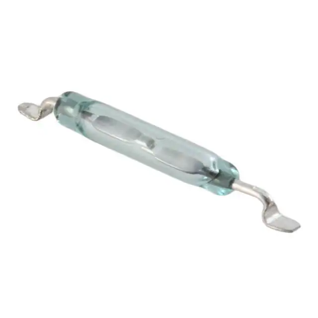
10.2mm Sub-miniature Surface Mount
RoHS
Description
The MDSM-10 Reed Switch is a sub-miniature, surface mounting,
normally open switch with a 10.16mm long x 1.80mm diameter
(0.400” x 0.071”) glass envelope, capable of switching 200Vdc at
10W.
This reed switch is a surface mount version of the MDSR-10. It
has high insulation resistance of 10¹² ohms minimum and low
contact resistance of less than 120milli-ohms.
Features & Benefits
■ Surface mounting normally
open switch
and have no effect on their
external environment
■ Capable of switching 200Vdc
or 0.5A at up to 10W
■ Low, stable contact
resistance
Agency Approvals
Agency
Agency File Number
Ampere-Turns Range
E47258
E471070
10-25 AT
■ Available sensitivity 10-25 AT
■ Hermetically sealed switch
contacts are not affected by
Note: Contact Littelfuse for specific agency approval ratings.
■ Zero operating power
required for contact closure
■ Excellent for switching
microcontroller logic level
loads
Applications
Dimensions
Dimensions in mm (inch)
Ø1.80
(.071) MAX
■ Low space requirement
1.00±0.10
(.045 +/-.004) TYP
■ Position Sensing
■ Security
■ Level Sensing
■ Metering
Switch Type
12.45±0.25
(.490±.010)
10.16
(.400)MAX
2.00 MAX
(.078)
15.62±0.10
(.615±.010)
Contact Form
A (SPST-NO)
Materials
Body: Glass
Leads: Tin-plated Ni-Fe wire
Note: SPST-NO = Single-pole, single-throw, normally open
2x0.00 MIN
(.000)
RECOMMENDED LAND PATTERN
1.30 (.051) TYP.
2.90 (.114) TYP.
11.20
(.441)
Note: Land pattern is Littelfuse recommendation only. User is responsible for proper PCB design.
Electrical Ratings
Contact Rating
Voltage
3
Current
3
Resistance
Capacitance
Temperature
1
Switching
2
Breakdown 4
Switching 2
Carry
Contact, Initial Insulation
Contact
Operating
Storage 5
W/VA - max.
Vdc - max.
Vac - max.
Vdc - min.
Adc - max.
Aac - max.
Adc - max.
Ω - max.
Ω - min.
pF - typ.
10
200
140
250
0.50
0.35
1.00
0.12
1012
0.2
°C
°C
-40 to +125
-65 to +125
Notes:
1. Contact rating - Product of the switching voltage and current should never exceed the wattage rating. Contact Littelfuse for additional load/life information.
2. When switching inductive and/or capacitive loads, the effects of transient voltages and/or currents should be considered. Refer to Application Notes AN108A and AN107 for details.
3. Electrical Load Life Expectancy - Contact Littelfuse with voltage, current values along with type of load.
4. Breakdown Voltage - per MIL-STD-202, Method 301.
5. Storage Temperature - Long time exposure at elevated temperature may degrade solderability of the leads.
1
© 2021 Littelfuse, Inc.
Specifications are subject to change without notice.
Revised: GD. 08/26/21
�Reed Switches Datasheet
MDSM-10
10.2mm Sub-miniature Surface Mount
Product Characteristics
Operating Characteristics
Operate Time
1
Release Time
1
Shock
0.5ms - max.
0.1ms - max.
11ms 1∕2 sine wave
2
Vibration
100G - max.
50-2000 Hertz
2
30G - max.
Resonant Frequency
6.5kHz - typ.
Magnetic Characteristics
Pull-In Range
3
Rating Sensitivity
4
Ampere Turns
10-25
Ampere Turns
15
Test Coil
L4989
Notes:
1. Operate (including bounce)/Release Time - per EIA/NARM RS-421-A, diode suppressed coil (Coil II).
2. Shock and Vibration - per EIA/NARM RS-421-A and MIL-STD-202.
3. Pull-In Range - Contact Littelfuse for narrower AT ranges available. These AT values are the before modification AT of the MDSR-10.
4. Rating Sensitivity - The value at which contact ratings and operating characteristics are determined. Derating may be required below this value.
Drop-Out vs. Pull-In Chart
Part Numbering System
MDSM-10R - 10-15
25
Max.
Drop-Out (AT, L4989 Coil)
20
15
Series
10
Packaging
R = Tape and Reel
B = Bulk
Min.
AT Range
10-25 AT
10-15 AT
15-20 AT
20-25 AT
5
0
0
5
10
15
20
25
30
35
Pull-In (AT, L4989 Coil)
Example:
10-15 AT product in Bulk
packaging is MDSM-10B-10-15
Note:
Note: Chart represents the range of Drop-Out, min to max, for a given Pull-in value of the
MDSR-10 prior to modification into the MDSM-10.
These AT values are the before-modification values of the bare reed switch.
Packaging
Packaging Option
Packaging Specification
Quantity
Quantity and Packaging Code
Taping Width
Tape and Reel
EIA-RS-481-1
3000
R
32mm
Bulk
N/A
200
B
N/A
2
© 2021 Littelfuse, Inc.
Specifications are subject to change without notice.
Revised: GD. 08/26/21
�Reed Switches Datasheet
MDSM-10
10.2mm Sub-miniature Surface Mount
TAPE DIMENSIONS mm (inch)
(.079)
2,00
(.059 +.004
-0 )
(.315)
8,00
Ø1,50+0,10
-0
(.069)
1,75
(.157)
4,00
7.5°
(.559)
14,20
(.240)
6,10
(1.118)
28,40
(.670)
17,02
(1.260)
32,00
(.830)
21,08
(.079)
Ø2,00
(.067 +.006
-.002 )
+0,15
-0,05
Ø1,70
(.240)
6,10
(.059 +.004
-0 )
(.016)
0,41
Ø1,50+0,10
-0
7.5°
3.0°
(.075)
1,90
(.046)
1,17
(.111)
2,82
(.084)
2,13
1. ALL TAPE & SPROCKET HOLE DIMENSIONS
ARE PER EIA-481 UNLESS NOTED
2. ALL POCKET DIMENSIONS ARE ±(.004") 0,10mm
3. ALL DIMENSIONS ARE TO INSIDE OF POCKET
REEL DIMENSIONS mm (inch)
+.010
(12.992-.030 )
330,00 +0,25
(3.937±.020)
100,0±0,50
(1.512)
38,4 MAX.
)
16
±.0 .4
27 ±0
( .8 21,0
Ø
(1.276+.008
)
-0
(32,4 +0.2
)
-0
12
0
°T
YP
.
(.075±.016)
1,9±0.4 TYP.
-0,76
MEASURED AT HUB
(.512±.008)
Ø13,0±0.2
Disclaimer Notice - Information furnished is believed to be accurate and reliable. However, users should independently evaluate the suitability of and test each product selected for their own applications. Littelfuse products are
not designed for, and may not be used in, all applications. Read complete Disclaimer Notice at: www.littelfuse.com/disclaimer-electronics.
3
© 2021 Littelfuse, Inc.
Specifications are subject to change without notice.
Revised: GD. 08/26/21
�