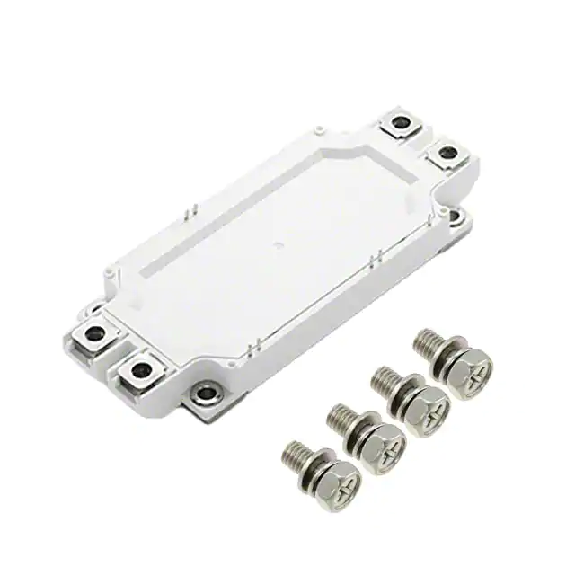
Power Module
600V 600A IGBT Module
MG06600WB-BN4MM
RoHS
Features
• H
� igh short circuit
capability, self limiting
short circuit current
• F
� ree wheeling diodes
with fast and soft reverse
recovery
• V
� CE(sat) with positive
temperature coefficient
• �Low switching losses
• F
� ast switching and short
tail current
Applications
• H
� igh frequency switching
application
• M
� otion/servo control
supplies
• �Medical applications
• �UPS systems
Module Characteristics (TJ = 25°C, unless otherwise specified)
Symbol
Parameters
TJ max
Max. Junction Temperature
Test Conditions
Min
Typ
Max
Unit
175
°C
TJ op
Operating Temperature
-40
150
°C
Tstg
Storage Temperature
-40
125
°C
Visol
Insulation Test Voltage
CTI
Comparative Tracking Index
AC, t=1min
3000
V
250
Torque
Module-to-Sink
Recommended (M5)
2.5
Torque
Module Electrodes
Recommended (M6)
3
Weight
5
N·m
5
N·m
350
g
Values
Unit
Absolute Maximum Ratings (TJ = 25°C, unless otherwise specified)
Symbol
Parameters
Test Conditions
TJ=25°C
IGBT
VCES
Collector - Emitter Voltage
VGES
Gate - Emitter Voltage
IC
DC Collector Current
ICM
Repetitive Peak Collector Current
Ptot
Power Dissipation Per IGBT
600
V
±20
V
TC=25°C
700
A
TC=50°C
600
A
tp=1ms
1200
A
1500
W
Diode
VRRM
Repetitive Reverse Voltage
IF(AV)
Average Forward Current
IFRM
Repetitive Peak Forward Current
I2t
MG06600WB-BN4MM
TJ=25°C
600
V
TC=25°C
700
A
TC=50°C
600
A
tp=1ms
1200
A
TJ =125°C, t=10ms, VR=0V
17000
A 2s
196
©2016 Littelfuse, Inc
Specifications are subject to change without notice.
Revised:10/05/16
�Power Module
600V 600A IGBT Module
Electrical and Thermal Specifications (TJ = 25°C, unless otherwise specified)
Symbol
Parameters
Test Conditions
Min
Typ
Max
Unit
Gate - Emitter Threshold Voltage
VCE=VGE, IC=9.6mA
4.9
Collector - Emitter
IC=600A, VGE=15V, TJ=25°C
1.45
5.8
6.5
V
Saturation Voltage
IC=600A, VGE=15V, TJ=125°C
1.6
IGBT
VGE(th)
VCE(sat)
IICES
Collector Leakage Current
IGES
Gate Leakage Current
RGint
Integrated Gate Resistor
Qge
Gate Charge
Cies
Input Capacitance
Cres
Reverse Transfer Capacitance
td(on)
1
mA
VCE=600V, VGE=0V, TJ=125°C
5
mA
400
nA
VCE=0V, VGE=±15V, TJ=125°C
VCE=25V, VGE=0V, f =1MHz
Rise Time
td(off)
Turn - off Delay Time
IC=600A
tf
Fall Time
VGE=±15V
VCC=300V
RG =2.4Ω
Inductive Load
Turn - on Energy
Turn - off Energy
ISC
Short Circuit Current
RthJC
-400
VCE=300V, IC=600A , VGE=±15V
tr
Eoff
V
VCE=600V, VGE=0V, TJ=25°C
Turn - on Delay Time
Eon
V
0.68
Ω
6.5
μC
39
nF
1.15
nF
TJ=25°C
100
ns
TJ=125°C
110
ns
TJ=25°C
90
ns
TJ=125°C
95
ns
TJ=25°C
670
ns
TJ=125°C
710
ns
TJ=25°C
70
ns
TJ=125°C
75
ns
TJ=25°C
8.9
mJ
TJ=125°C
9.9
mJ
TJ=25°C
21.5
mJ
TJ=125°C
25
mJ
tpsc≤6μS , VGE=15V; TJ=125°C , VCC=360V
3000
Junction-to-Case Thermal Resistance (Per IGBT)
A
0.10
K/W
Diode
VF
Forward Voltage
tRR
Reverse Recovery Time
IRRM
Max. Reverse Recovery Current
Erec
Reverse Recovery Energy
RthJCD
IF=600A, VGE=0V, TJ =25°C
1.55
V
IF=600A, VGE=0V, TJ =125°C
1.5
V
IF=600A, VR=300V
diF/dt=-6000A/µs
TJ=125°C
400
ns
300
A
9.3
mJ
Junction-to-Case Thermal Resistance (Per Diode)
0.16
K/W
Max
Unit
NTC Characteristics (TJ = 25°C, unless otherwise specified)
Symbol
Parameters
Test Conditions
R25
Resistance
Tc=25°C
B25/50
MG06600WB-BN4MM
2
97
Min
Typ
5
KΩ
3375
K
©2016 Littelfuse, Inc
Specifications are subject to change without notice.
Revised:10/05/16
�Power Module
600V 600A IGBT Module
Figure 1: �Typical Output Characteristics
for IGBT Inverter
Figure 2: �Typical Output Characteristics
for IGBT Inverter
1200
1200
VGE =19V
VGE =17V
VGE =15V
VGE =13V
VGE =11V
VGE = 9V
VGE =15V
960
720
TJ =25°C
IC (A)
IC (A)
960
720
TJ =125°C
480
480
TJ =125°C
240
240
0
0
0.4
0.8
1.2 1.6
VCE˄V˅
2.0
0
2.4
Figure 3: T
� ypical Transfer Characteristics
for IGBT Inverter
0 0.5 1.0 1.5 2.0 2.5 3.0 3.5 4.0 4.5 5.0
VCE˄V˅
Figure 4: Switching Energy vs. Gate Resistor
for IGBT Inverter
1200
200
VCC=300V
IC=600A
VGE=±15V
TJ =125°C
VCE =20V
160
960
120
Eon Eoff (mJ)
IC (A)
TJ =25°C
720
480
TJ =125°C
80
Eoff
40
240
0
5
0
6
7
9
8
VGE˄V˅
10
11
Figure 5: �Switching Energy vs. Collector Current
for IGBT Inverter
70
60
50
8
12
16
RG˄Ω˅
20
24
1200
1000
Eoff
800
30
20
600
RG=2.4Ω
VGE=±15V
TJ =125°C
400
10
MG06600WB-BN4MM
4
1400
VCE=300V
RG=2.4Ω
VGE=±15V
TJ =125°C
40
0
0
0
Figure 6: R
� everse Biased Safe Operating Area
for IGBT Inverter
IC (A)
Eon Eoff (mJ)
Eon
Eon
200
400
600 800
IC˄A˅
200
0
1000 1200
3
98
0
100
200
300 400 500 600 700
VCE˄V˅
©2016 Littelfuse, Inc
Specifications are subject to change without notice.
Revised:10/05/16
�Power Module
600V 600A IGBT Module
Figure 7: �Diode Forward Characteristics
for Diode Inverter
Figure 8: S
� witching Energy vs. Gate Resistort
for Diode Inverter
1200
14
IF=600A
VCE=300V
TJ =125°C
12
960
Erec (mJ)
10
IF (A)
720
480
TJ =125°C
240
0
8
6
4
2
TJ =25°C
0
0
0.4
0.8
1.2
VF˄V˅
1.6
2.0
Figure 9: Transient Thermal Impedance of
Diode and IGBT Inverter
0
4
8
12
16
RG˄Ω˅
20
24
Figure 10: N
� TC Characteristics
1
100000
0.1
10000
IGBT
R (¡)
ZthJC (K/W)
Diode
0.01
R
1000
100
0
0.001
0.001
0.01
0.1
1
10
Rectangular Pulse Duration (seconds)
20
40
80 100 120 140 160
60
TC˄°C˅
Circuit Diagram
MG06600WB-BN4MM
4
99
©2016 Littelfuse, Inc
Specifications are subject to change without notice.
Revised:10/05/16
�Power Module
600V 600A IGBT Module
Dimensions-Package WB
The foot pins are in gold / nickel coating
Packing Options
Part Number
Marking
Weight
Packing Mode
M.O.Q
MG06600WB-BN4MM
MG06600WB-BN4MM
350g
Bulk Pack
60
Part Marking System
Part Numbering System
MG06600 WB - B N4 MM
PRODUCT TYPE
M: Power Module
MODULE TYPE
G: IGBT
VOLTAGE RATING
06: 600V
CURRENT RATING
MG06600WB-BN4MM
ASSEMBLY SITE
WAFER TYPE
LOT NUMBER
CIRCUIT TYPE
2x(IGBT+FWD)
Space
reserved
for QR
code
PACKAGE TYPE
600: 600A
MG06600WB-BN4MM
5
100
©2016 Littelfuse, Inc
Specifications are subject to change without notice.
Revised:10/05/16
�
很抱歉,暂时无法提供与“MG06600WB-BN4MM”相匹配的价格&库存,您可以联系我们找货
免费人工找货