Battery Mini-Breakers (Thermal Cutoff Devices)
Metal Hybrid PPTC > MHP Series
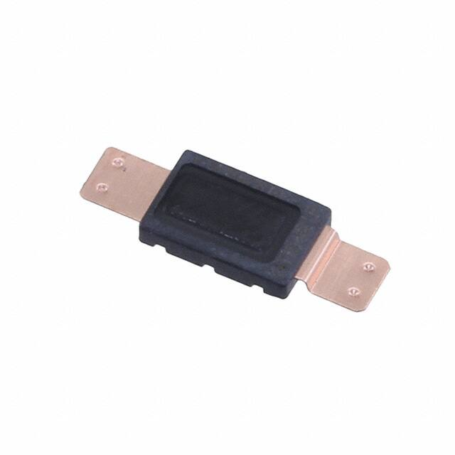
MHP-TAT18 Series Breaker
RoHS
Description
The new Metal Hybrid PPTC device, MHP-TAT18, offers a
9VDC rating and a higher current rating than typical MHPTAM devices. MHP-TAT18 helps to meet the battery safety
requirements of higher-capacity Lithium (Ion) Polymer and
prismatic batteries found in most mobile devices such as
laptop PC’s, tablets, and smart phones. MHP technology
connects a bimetal protector in parallel with a Polymeric
Positive Temperature Coefficient (PPTC) device. The PPTC
device to act as a heater and to help keep the bimetal
latched until the fault is removed. The resulting MHPTAT18 series helps to provide resettable overtemperature
protection.
Circuit Diagram
Features
• Compact size (L: 5.8mm
x W: 3.80mm x H:
1.15mm) allows for ultrathin battery pack designs
• High current capacity
with low resistance
• Overtemperature and
overcurrent protection
• Multiple activation
temperature ratings
(72°C, 77°C, 82°C, 85°C,
90°C)
• Evaluated to UL 60730-1
and UL 60730-2-9, CAN/
CSA E60730-1, CAN/CSA
E730-2-9 and IEC 607301 and IEC 60730-2-9.
Applications
Agency Approvals
Agency
Battery cell protection for high-capacity Lithium Polymer
and Prismatic cells used in:
• Gaming PCs
• Notebook PCs
• Ultra-book
• Tablets
• Battery-powered portable devices
Agency File Number
E349829
DK-74156-M1-UL
Typical Electrical Ratings
Part Description
MHP-TAT18-9-72N
MHP-TAT18-9-77N
MHP-TAT18-9-82N
MHP-TAT18-9-85N
MHP-TAT18-9-90N
Operation Temperature
72°C+/-5°C
77°C+/-5°C
82°C+/-5°C
85°C+/-5°C
90°C+/-5°C
Ordering Part Number
RF4785-000
RF4668-000
RF4786-000
RF4629-000
RF4787-000
≥40°C
≥40°C
≥40°C
≥40°C
≥40°C
Reset Temperature
Hold Current
Contact Rating
18A@25°C
DC 9V/30A, 6000 Cycles
Maximum Breaking Current
DC 5V/80A, 100 Cycles
Maximum Open Voltage
DC 28V/30A, 100 Cycles
Minimum Hold Voltage
Maximum Leakage Current
Resistance
3V
200mA@25°C
2.5 milliohms Max.
Precautions for Electrical Characteristics:
a. Device electrical characteristics may change depending on installation conditions. Users should independently evaluate the suitability of and test each product in their own application.
b. If any terminal or lead extensions are added to the device, especially in the case of high current discharging, the device performance may be negatively impacted due to variations
in welding methods or materials. Please avoid designs that might cause heat to be generated around the joints of the lead extensions or on the extended terminals.
c. SMT solder reflow, wave-soldering and manual soldering irons are not permitted.
© 2021 Littelfuse, Inc.
Specifications are subject to change without notice.
Revised: 09/03/21
�Battery Mini-Breakers (Thermal Cutoff Devices)
Metal Hybrid PPTC > MHP Series
Dimensions
A
B
C
D
E
Min
Max
Min
Max
Min
Max
Min
Max
Min
Max
10.9mm
11.5mm
1.05mm
1.15mm
3.75mm
3.85mm
2.6mm
2.8mm
2.6mm
2.8mm
A
5.8
D
Ø0
E
C
2.8
TAT18-
1.2
.4
1.2
2.8
4-
0.7
0.7
(0.2)
(0.2)
0.12 ± 0.01
0.12 ± 0.01
0.1
0.1
B
Notes:
Unspecified dimensions, tolerance should be +/-0.1mm
Dimensions in brackets are for reference
Current Vs. Temperature Curves
Part Marking System
30
28
26
24
Year Code
Current (A)
22
20
18
16
MHP-TA T18-9-90 (Typical Part)
14
MHP-TA T18-9-85 (Typical Part)
12
MHP-TA T18-9-82 (Typical Part)
10
MHP-TA T18-9-77 (Typical Part)
MHP-TA T18-9-72 (Typical Part)
8
6
20
25
30
35
40
45
50
55
60
65
70
75
1
7
2
3
2
H
5
Week Code: 01~52
Day Code: 1~7
Assembly Machine Code: A~Z
Marking Machine Code: 1~9
Company Logo
Temperature (°C)
TAT 18-85 LF
The current versus temperature curve was derived from placing test samples in an oven at
25°C, 40°C, 60°C, 65°C, and 70°C, increasing current flow through the sample at a rate of
0.1A/minute and recording the current value when the sample trips.
Nominal Activation Temperature
72, 77, 82, 85, 90
Nominal Hold Current at
Room Temperature
Product Group
© 2021 Littelfuse, Inc.
Specifications are subject to change without notice.
Revised: 09/03/21
�Battery Mini-Breakers (Thermal Cutoff Devices)
Metal Hybrid PPTC > MHP Series
Application Environment
Part Naming System
The device is intended to be used for applications which
are common for general electronic devices. Usage in
any of the special environments or conditions as listed
below may adversely impact the device performance and
therefore users should carefully consider conditions of use
of the end product and the potential impact on reliability
or performance when incorporating this device into any
design to carefully examine the actual performance and
reliability of the device.
• �Environment where the devices are exposed to water,
oil, chemical solutions, and/or organic solvents.
• �Installation in an area close to a heat source or
adjacent to or near flammable objects such as
plastic wires.
• �Environment in which the device is constrained by
pressure, sealing or resin coating.
• �Environment where water condenses on the device.
• �Environment with salt air or with corrosive gas such as
CL2, H2S, NH3, SO2, and NOX.
• �Environment with grit and dust and/or under direct
sunlight.
• �Environment outside of recommended operating
temperature.
MHP TAT 18 9 77 N
TERMINAL TYPE
N: Non Dimple
(BLANK): With Dimple
NOMINAL ACTIVATION
TEMPERATURE
72, 77, 82, 85, 90
CONTACT VOLTAGE RATING
NOMINAL HOLD CURRENT
AT ROOM TEMPERATURE
PRODUCT GROUP
SERIES NAME
Packaging
Packaging Option
Quantity
Quantity & Packaging Code
20,000 pcs. Minimum
1000 pcs/bag
1 bag per inner box 20 inner box in 1 outer box
Precautions for Rating
a. The power supply voltage must be less than or equal to
the rated voltage of the device. Operation above the voltage
rating may result in device damage, smoke or flame.
b. Designs must be selected in such a manner that the
device hold current is higher than the normal current value in
the circuit. Selecting device hold current that is too low for
the application may interrupt the circuit under normal usage
conditions.
c. This product should not be used in an application where
the maximum short circuit current available exceeds the
rated maximum breaking current of the product.
© 2021 Littelfuse, Inc.
Specifications are subject to change without notice.
Revised: 09/03/21
d. The devices are intended for protection against damage
caused by occasional over current or over temperature fault
conditions and should not be used when repeated fault
conditions or prolonged trip events are anticipated.
e. The devices may not perform as specified if mechanical
pressure is added while the device is in the tripped state
or exposed to temperature conditions over 100°C or in
temperature conditions under -30°C.
�Battery Mini-Breakers (Thermal Cutoff Devices)
Metal Hybrid PPTC > MHP Series
Handling Precautions
a. The device is composed of plastic parts, please do not
clamp or dent the housing with a tool as this might cause a
resistance increase and product damage.
b. When welding product terminals or mounting the breaker
on battery (cell), please be careful not to apply excessive
bending, twisting or force on the product and terminals.
The excessive stress might cause a resistance increase or
product damage.
Please refer to following cautions.
• �Do not apply more than 10N bend force to product.
(Fig. 1)
• �Do not apply more than 1.5cN*m twist torque to the
product. (Fig. 2)
• �Do not apply more than 20N deflection force to product.
(Fig. 3)
• �Do not apply more than 2N force to the terminals.
(Fig. 4)
• �Do not apply more than 0.6cN*m twisting torque to the
terminals. (Fig. 5)
• �Do not bend the terminals more than 45° at the end.
(Fig. 6)
• �Should not twist terminals more than 20°C with breaker
body fixed.
c. Product terminals can be welded using direct welding
and series welding methods. In either case, please use a
suitable Jig so that the device will not be subjected to the
stress conditions listed above.
d. Pull strength and detach strength of the terminal welds
are per user requirements. However, if the welding is
controlled by resistance, the measurement should be made
as close as possible to the weld point by a “4-point clip
method” using milliohm meter to ensure accuracy.
e. Please avoid putting the stress on the device, as listed
above, when a jig, fitting or additional welding process is
used. Please re-confirm the resistance value whenever a
new process is added.
Fig-1
Fig-2
Fig-3
Fig-4
Fig-5
Fig-6
Disclaimer Notice - Information furnished is believed to be accurate and reliable. However, users should independently evaluate the suitability of and
test each product selected for their own applications. Littelfuse products are not designed for, and may not be used in, all applications. Read complete
Disclaimer Notice at www.littelfuse.com/disclaimer-electronics.
© 2021 Littelfuse, Inc.
Specifications are subject to change without notice.
Revised: 09/03/21
�