Ethernet/10BaseT/100BaseT/1000BaseT Protector
Ethernet/10BaseT/100BaseT/1000BaseT
Protector
The DO-214AA SIDACtor Ethernet protection series is intended for applications sensitive to
load values. Typically, high speed connections require a lower capacitance. CO values are
40% lower than standard devices.
SIDACtor devices are used to enable equipment to meet various regulatory requirements
including GR 1089, ITU K.20, K.21 and K.45, IEC 60950, UL 60950, and TIA-968-A
(formerly known as FCC Part 68).
Electrical Parameters
Part
Number *
VDRM
Volts
VS
Volts
VT
Volts
IDRM
µAmps
IS
mAmps
IT
Amps
IH
mAmps
CO
pF
P0220S_
15
32
4
5
800
P0642S_**
58
77
4
5
800
2.2
50
50
2.2
120
P0722S_**
65
88
4
5
25
800
2.2
120
P0902S_**
75
98
4
25
5
800
2.2
120
P1102S_**
90
130
25
4
5
800
2.2
120
20
P1302S_
120
P1402S_
140
160
4
5
800
2.2
150
20
180
4
5
800
2.2
120
P1502S_
20
140
180
4
5
800
2.2
150
20
P1802S_
170
220
4
5
800
2.2
150
15
P2302S_
190
260
4
5
800
2.2
150
15
P2602S_
220
300
4
5
800
2.2
150
15
P3002S_
280
360
4
5
800
2.2
120
15
P3502S_
320
400
4
5
800
2.2
150
15
P4802S_
440
600
4
5
800
2.2
120
15
* For surge ratings, see table below.
** Contact factory for release date.
General Notes:
• All measurements are made at an ambient temperature of 25 °C. IPP applies to -40 °C through +85 °C temperature range.
• IPP is a repetitive surge rating and is guaranteed for the life of the product.
• Listed SIDACtor devices are bi-directional. All electrical parameters and surge ratings apply to forward and reverse polarities.
• VDRM is measured at IDRM.
• VS is measured at 100 V/µs.
• Special voltage (VS and VDRM) and holding current (IH) requirements are available upon request.
• Off-state capacitance (CO) is measured at 1 MHz with a 2 V bias.
Surge Ratings
Series
IPP
2x10 µs
Amps
IPP
8x20 µs
Amps
A
150
150
90
50
45
20
500
B
250
250
150
100
80
30
500
http://www.littelfuse.com
+1 972-580-7777
IPP
10x160 µs
Amps
IPP
10x560 µs
Amps
2 - 14
IPP
10x1000 µs
Amps
ITSM
60 Hz
Amps
di/dt
Amps/µs
© 2004 Littelfuse, Inc.
SIDACtor® Data Book and Design Guide
�Ethernet/10BaseT/100BaseT/1000BaseT Protector
Thermal Considerations
Symbol
TJ
Operating Junction Temperature Range
-40 to +150
°C
TS
Storage Temperature Range
-65 to +150
°C
90
°C/W
RθJA
Parameter
Value
Thermal Resistance: Junction to Ambient
Unit
IPP – Peak Pulse Current – %IPP
+I
+I
IITT
ISS
IH
IDRM
-V
-V
+V
+V
V
VTT
V
VDRM
DRM
V
VS
S
Peak
Value
100
tr = rise time to peak value
td = decay time to half value
Waveform = tr x td
50
Half Value
0
0
tr
td
t – Time (µs)
-I
-I
V-I Characteristics
tr x td Pulse Wave-form
IH
8
6
25 ˚C
4
2
IH (TC = 25 ˚C)
10
Ratio of
Percent of VS Change – %
14
12
0
-4
2.0
1.8
1.6
1.4
25 ˚C
1.2
1.0
0.8
0.6
0.4
-40 -20 0
-6
-8
-40 -20
0
20 40 60 80 100 120 140 160
Case Temperature (TC) – ˚C
20 40 60 80 100 120 140 160
Junction Temperature (TJ) – ˚C
Normalized VS Change versus Junction Temperature
© 2004 Littelfuse, Inc.
SIDACtor® Data Book and Design Guide
Normalized DC Holding Current versus Case Temperature
2 - 15
http://www.littelfuse.com
+1 972-580-7777
Data Sheets
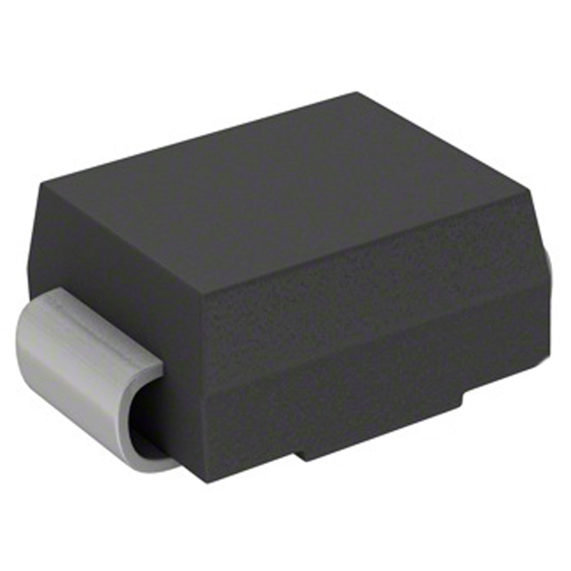
Package
DO-214AA
�
很抱歉,暂时无法提供与“P0642SARP”相匹配的价格&库存,您可以联系我们找货
免费人工找货