SIDACtor® Protection Thyristors
SLIC Protection
Fixed Voltage Q2L Series 3.3x3.3 QFN
RoHS
Pb e3
Description
Fixed Voltage Q2L Series are uni-directional SIDACtor®
thyristors designed to protect SLICs (Subscriber Line
Interface Circuit) from damaging overvoltage transients.
The series provides single line protection using a fixed voltage
switching component for negative surges. All positive surges
are routed through an internal diode to a ground reference.
The small size of the Q2L makes it ideal for high density
applications.
Features and Benefits
Agency Approvals
surged in excess of
ratings
• Integrated diode for
positive voltage surges
Agency
• RoHS Compliant and
Halogen-Free
• �Low profile
Agency File Number
• S
� mall footprint QFN
Package
E133083
• Pb-free E3 means 2nd
level interconnect is
• �Low on-state voltage
Pb-free and the terminal
• �Does not degrade surge
finish material is tin(Sn)
capability after multiple
(IPC/JEDEC J-STDsurge events within limit.
609A.01)
• Fails short circuit when
Pinout Designation
Cathode
Indicator
Applicable Global Standards
Schematic Symbol
(T/R)
• TIA-968-A
• GR-1089 Intra-building
• TIA-968-B
• IEC 61000-4-5 2nd
editin
• ITU K.20/21/Enhanced
Level
(G)
• YD/T 950
• ITU K.20/21/Basic Level
• YD/T 993
• GR 1089 Inter-building
• YD/T 1082
Additional Information
Datasheet
Samples
Resources
Electrical Characteristics
VDRM
VS
@IDRM=5µA
@100V/µs
V min
58
P71C
P0901Q22CLRP
VT
Capacitance
@1MHz @ 2V bias
IH
IS
IT
V max
mA min
mA max
A max
V max
V max
pF min
pF max
77
120
800
2.2
4
5
35
75
65
88
120
800
2.2
4
5
25
45
P91C
75
98
120
800
2.2
4
5
55
85
P1101Q22CLRP
P10C
95
130
120
800
2.2
4
5
50
75
P1301Q22CLRP
P13C
120
160
120
800
2.2
4
5
45
70
P1701Q22CLRP
P17C
160
200
120
800
2.2
4
5
45
70
Part Number
Marking
P0641Q22CLRP
P61C
P0721Q22CLRP
@IT=2.2 Amps
VF
Notes:
- Absolute maximum ratings measured at TA= 25ºC (unless otherwise noted).
- Components are not appropriate for positive ringing systems.
© 2020 Littelfuse, Inc.
Specifications are subject to change without notice.
Revised: 03/05/20
�SIDACtor® Protection Thyristors
SLIC Protection
Surge Ratings
ITSM
Ipp
di/dt
Series
2/10µs
1.2/50µs/8/20µs
10/160µs
10/560µs
10/1000µs
50 / 60Hz
C
A min
500
A min
400
A min
200
A min
150
A min
100
A min
30
Amps/µs max
500
Notes:
- Peak pulse current rating (IPP) is repetitive and guaranteed for the life of the product that remains in thermal equilibrium.
- IPP ratings applicable over temperature range of -40ºC to +85ºC
- The component must initially be in thermal equilibrium with -40°C < TJ < +150°C
Thermal Considerations
Package
Symbol
3.3x3.3 QFN
Parameter
Value
Unit
°C
TJ
Operating Junction Temperature Range
-40 to +150
TS
Storage Temperature Range
-65 to +150
°C
120
°C/W
R0JA
Thermal Resistance: Junction to Ambient
V-I Characteristics
tr x td Pulse Waveform
VS VDRM
VF
IPP – Peak Pulse Current – %IPP
+I
VT
-V
IDRM
+V
IH
IS
Peak
Value
100
IT
tr = rise time to peak value
td = decay time to half value
Waveform = tr x td
50
Half Value
0
0
td
tr
t – Time (µs)
-I
Normalized DC Holding Current vs. Case Temperature
10
IH
8
6
25 °C
4
IH (TC = 25ºC)
2.0
14
12
Ratio of
Percent of VS Change – %
Normalized VS Change vs. Junction Temperature
2
0
-4
-6
1.8
1.6
1.4
1.0
0.8
0.6
0.4
-8
-40 -20
0
20 40 60 80 100 120 140 160
Junction Temperature (TJ) – °C
25°C
1.2
-40
-20
0
20
40
60
80
100 120 140
160
Case Temperature (TC) - ºC
© 2020 Littelfuse, Inc.
Specifications are subject to change without notice.
Revised: 03/05/20
�SIDACtor® Protection Thyristors
SLIC Protection
Soldering Parameters
Pb-Free assembly
- Temperature Min (Ts(min))
+150°C
- Temperature Max (Ts(max))
+200°C
- Time (Min to Max) (ts)
60-180 secs.
Average ramp up rate (Liquidus Temp (TL) to peak)
3°C/sec. Max.
TS(max) to TL - Ramp-up Rate
3°C/sec. Max.
Pre Heat
Reflow
- Temperature (TL) (Liquidus)
+217°C
- Temperature (tL)
60-150 secs.
Peak Temp (TP)
+260(+0/-5)°C
Time within 5°C of actual Peak Temp (tp)
30 secs. Max.
Ramp-down Rate
6°C/sec. Max.
Time 25°C to Peak Temp (TP)
8 min. Max.
Do not exceed
+260°C
Physical Specifications
TP
Copper Alloy
Terminal Finish
100% Matte-Tin Plated
UL Recognized epoxy meeting flammability
classification V-0
Critical Zone
TL to TP
Ramp-up
TL
T S(max)
tL
Ramp-down
Preheat
T S(min)
tS
25
time to peak temperature
(t 25ºC to peak)
Time
High Temp Voltage
Blocking
80% Rated VDRM (VDC ) +125°C or +150°C, 504 or
1008 hrs. MIL-STD-750 (Method 1040) JEDEC,
JESD22-A-101
Temp Cycling
-65°C to +150°C, 15 min. dwell, 10 up to 100
cycles. MIL-STD-750 (Method 1051) EIA/JEDEC,
JESD22-A104
Biased Temp &
Humidity
High Temp Storage
Low Temp Storage
Resistance to Solder
Heat
Moisture Sensitivity
Level
Part Numbering
52 VDC (+85°C) 85%RH, 504 up to 1008 hrs. EIA/
JEDEC, JESD22-A-101
+150°C 1008 hrs. MIL-STD-750 (Method 1031)
JEDEC, JESD22-A-101
-65°C, 1008 hrs.
0°C to +100°C, 5 min. dwell, 10 sec. transfer,
10 cycles. MIL-STD-750 (Method 1056) JEDEC,
JESD22-A-106
Thermal Shock
+260°C, 30 secs. MIL-STD-750 (Method 2031)
85%RH, +85°C, 168 hrs., 3 reflow cycles (+260°C
Peak). JEDEC-J-STD-020, Level 1
Part Marking
P xxx 1 Q22 C L RP
Cathode Indicator
TYPE
P=SIDACtor
REEL PACK
MEDIAN VOLTAGE
RoHS COMPLIANT
CONSTRUCTION
VARIABLE
IPP RATING
PACKAGE TYPE
tP
Environmental Specifications
Lead Material
Body Material
Figure 1
Temperature
Reflow Condition
XXXX
XXXXX
Part Marking Code
(Refer to Electrical Characteristics Table)
Date Code
Terminals on Back
© 2020 Littelfuse, Inc.
Specifications are subject to change without notice.
Revised: 03/05/20
�SIDACtor® Protection Thyristors
SLIC Protection
Dimensions — 3.3x3.3 QFN
BOTTOM VIEW
TOP VIEW
C
A
B
END VIEW
Dimensions
E
J
A
B
C
E
F
H
J
K1
K2
M1
M2
N1
N2
F
3.4
2.15
2.23
SIDE VIEW
H
0.585
N2
N1
M1
K1
K2
M2
Inches
Min
0.126
0.126
0.075
0.011
0.088
0.035
0.000
0.004
0.004
0.063
0.045
0.095
0.082
Millimeters
Min
Max
3.200
3.400
3.200
3.400
1.900
2.100
0.285
0.485
2.230
2.430
0.900
1.100
0.000
0.200
0.100
0.300
0.100
0.300
1.610
1.810
1.153
1.353
2.420
2.620
2.080
2.280
Max
0.134
0.134
0.083
0.019
0.096
0.043
0.008
0.012
0.012
0.071
0.053
0.103
0.090
Recommended
Soldering Pad Outline
(Reference Only)
Packing Options
Package Type
Description
Quantity
Added Suffix
Industry Standard
Q22
3.3x3.3 QFN Tape and Reel Pack
5000
RP
EIA-481-D
Tape and Reel Dimension — 3.3x3.3 QFN
Reel Dimension
Description
C
A
D
N
W1
B
Tape Leader and Trailer Dimensions
CARRIER TAPE
END
COVER TAPE
START
TRAILER
160mm MIN
LEADER
400mm MIN
Tape Dimension Items
D0
P0
P2
T
CARRIER TAPE
D1
B0
W0
K0
CATHODE
INDICATOR
P1
E1
F
E2
W
Inches
Millimeters
Min
Max
Min
Max
N/A
12.992
N/A
330.0
A
Reel Diameter
B
Drive Spoke Width
0.059
N/A
1.50
C
Arbor Hole Diameter
0.504
0.531
12.80
13.50
N/A
N/A
D
Drive Spoke Diameter
0.795
N/A
20.20
N
Hub Diameter
1.969
N/A
50.00
N/A
W1
Reel Inner Width at Hub
0.488
0.567
12.40
14.40
A0
Pocket Width at bottom
0.138
0.146
3.50
3.70
B0
Pocket Length at bottom
0.138
0.146
3.50
3.70
D0
Feed Hole Diameter
0.059
0.063
1.50
1.60
D1
Pocket Hole Diameter
0.059
N/A
1.50
N/A
E1
Feed hole position 1
0.065
0.073
1.65
1.85
E2
Feed hole position 2
0.400
0.408
10.15
10.35
F
Feed hole center-Pocket hole
0.215
0.219
5.45
5.55
K0
Pocket Depth
0.039
0.051
1.00
1.30
P0
Feed Hole Pitch
0.153
0.161
3.90
4.10
P1
Component Spacing
0.311
0.319
7.90
8.10
P2
Feed hole center-Pocket hole
0.077
0.081
1.95
2.05
T
Carrier Tape Thickness
0.010
0.014
0.25
0.35
W
Embossed Carrier Tape Width
0.453
0.484
11.50
12.30
W0
Cover Tape Width
0.358
0.366
9.10
9.30
A0
COVER TAPE
Disclaimer Notice - Information furnished is believed to be accurate and reliable. However, users should independently evaluate the suitability of and test each product selected for their own applications. Littelfuse products are
not designed for, and may not be used in, all applications. Read complete Disclaimer Notice at www.littelfuse.com/disclaimer-electronics.
© 2020 Littelfuse, Inc.
Specifications are subject to change without notice.
Revised: 03/05/20
�
很抱歉,暂时无法提供与“P1101Q22CLRP”相匹配的价格&库存,您可以联系我们找货
免费人工找货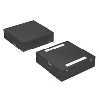


 工商网监
湘ICP备2023018690号
工商网监
湘ICP备2023018690号
