CATV Line Amplifiers/Power Inserters 3 kA SIDACtor® Device
RoHS
2
This SIDACtor device is a 3000 A solid state protection device offered in a non-isolated
TO-220 package. It protects equipment located in the severe surge environment of CATV
(Community Antenna TV) systems and antenna locations.
Electrical Parameters
Part
Number *
VDRM
Volts
VS
Volts
VT
Volts
IDRM
µAmps
IS
mAmps
IT
Amps **
IH
mAmps
50
P1500REL
140
180
4
5
800
2.2/25
P1900REL
140
220
4
5
800
2.2/25
50
P2300REL
180
260
4
5
800
2.2/25
50
* “L” in part number indicates RoHS compliance. For non-RoHS compliant device, delete “L” from part number.
For surge ratings, see table below.
** IT is a free air rating; heat sink IT rating is 25 A.
General Notes:
• All measurements are made at an ambient temperature of 25 °C. IPP applies to -40 °C through +85 °C temperature range.
• IPP is a repetitive surge rating and is guaranteed for the life of the product.
• Listed SIDACtor devices are bi-directional. All electrical parameters and surge ratings apply to forward and reverse polarities.
• VDRM is measured at IDRM.
• VS is measured at 100 V/µs.
• Special voltage (VS and VDRM) and holding current (IH) requirements are available upon request.
Surge Ratings in Amps
IPP
8x20 *
1.2x50 **
ITSM
50 / 60 Hz
di/dt
Series
Amps
Amps
Amps/µs
E
3000
400
500
* Current waveform in µs
** Voltage waveform in µs
Telecom Design Guide • © 2006 Littelfuse
3 - 89
www.littelfuse.com
SIDACtor Devices
1
�CATV Line Amplifiers/Power Inserters 3 kA SIDACtor® Device
Thermal Considerations
Package
Symbol
Pin2
TJ
Operating Junction Temperature Range
-40 to +150
°C
TS
Storage Temperature Range
-65 to +150
°C
TC
TO-220
Pin3
Pin1
Parameter
Value
Unit
Maximum Case Temperature
100
°C
RθJC *
Thermal Resistance: Junction to Case
1.7
°C/W
RθJA
Thermal Resistance: Junction to Ambient
56
°C/W
Pin2
* RθJC rating assumes the use of a heat sink and on state mode for extended time at 25 A, with average power dissipation of 29.125 W.
Capacitance Values
pF
Part Number
P1500REL
P1900REL
P2300REL
MIN
260
180
170
MAX
650
290
270
Note: Off-state capacitance (CO) is measured at 1 MHz with a 2 V bias.
IPP – Peak Pulse Current – %IPP
+I
IT
IS
IH
IDRM
-V
+V
VT
VDRM
VS
Peak
Value
100
tr = rise time to peak value
td = decay time to half value
Waveform = tr x td
50
Half Value
0
0
tr
td
t – Time (µs)
-I
14
12
10
IH
8
6
25 ˚C
4
2
IH (TC = 25 ˚C)
tr x td Pulse Waveform
Ratio of
Percent of VS Change – %
V-I Characteristics
0
-4
2.0
1.8
1.6
1.4
25 ˚C
1.2
1.0
0.8
0.6
0.4
-40 -20 0
-6
-8
-40 -20
0
20 40 60 80 100 120 140 160
Junction Temperature (TJ) – ˚C
Normalized VS Change versus Junction Temperature
www.littelfuse.com
20 40 60 80 100 120 140 160
Case Temperature (TC) – ˚C
Normalized DC Holding Current versus Case Temperature
3 - 90
© 2006 Littelfuse • Telecom Design Guide
�
很抱歉,暂时无法提供与“P1900REL”相匹配的价格&库存,您可以联系我们找货
免费人工找货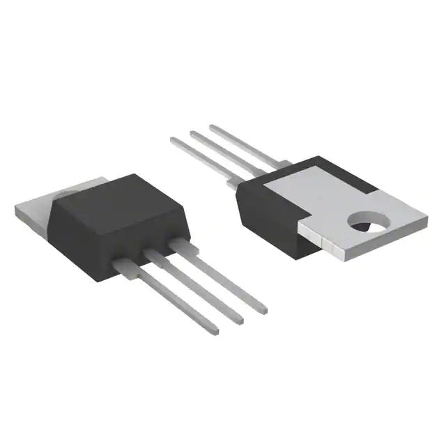


 工商网监
湘ICP备2023018690号
工商网监
湘ICP备2023018690号
